Blink codes for status led, Table 1-1: diagnostic led blink codes, Philips – Orion System MODGAS II User Manual
Page 6
Section 1
MODGAS II Controller
1-2
Overview and Wiring
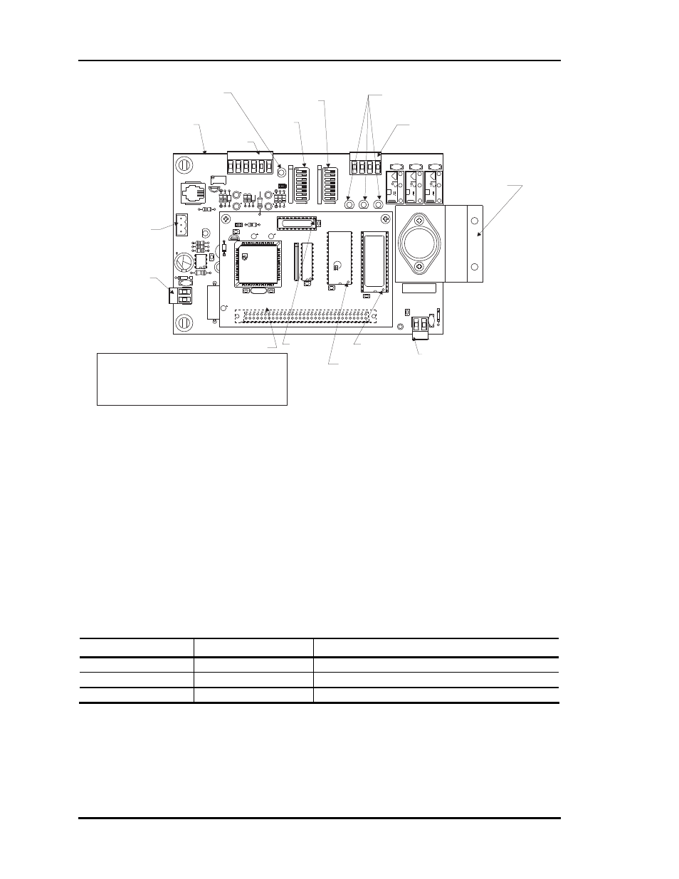
Figure 1-1: MODGAS II Controller Component Locations
Blink Codes for Status LED
The MODGAS II Controller uses an on-board LED to indicate various diagnostic conditions
during power-up and operation. The LED is labeled “STATUS”. Starting with power up, the LED
blink codes are as follows:
• One Blink
• Off for five seconds
• Blinks 30 times
• Blinks 3 times rapidly
• Status code repeatedly blinks every ten seconds to indicate controller status:
Priority
No. of Blinks
Status
Lowest 1
Normal
Operation
-
2
SAT Over High Limit
Highest
3
Bad SAT Sensor
Table 1-1: Diagnostic LED Blink Codes
Only the highest priority failure code will be shown. You must correct the highest priority alarm
before other problems will be indicated.
PHILIPS
EPROM
U3
U5
RAM
CX2
1
U2
R1
C3
U4
CX3
CX4
YS101818
552 PROCESSOR
BOARD
CX5
C1
U1
R2
CX1
CX6
WDOG
U6
PHILIPS
P1
C2
C4
V1
V3
K3
V2
K2
FT
K1
TB1
DISCHARGE
SETPOINT
F
F
1
1
O
O
F
F
RESET
LIMIT
AUX
COM
AUX
LO
SPD
FA
N
LO SPD
FAN
ADD
ADD
4
4
2
2
16
16
8
8
64
64
32
32
128
128
R4
GAS
VALVE
SER. #:
VOUT
D9
V5
C13
GND
TB4
POWER
YS101826PREV 1
MODULATING
GAS BOARD
PJ1
SHLD
RV1
ST
ATUS
P1
R8
RST
IN
J01
AUX
IN
GND
HEA
T
E
N
C2
R1
R3
R1
P
D2
R9
C1
SA
T
+VDC
VR1
R7
D1
R15
P
I2C
IN
TB2
R
T
V4
GND
24VAC
D8
U5
C7
R25
R26
R26
C6
POWER
TB3
Relay Output
Terminals
Relay Output
LEDs
Analog Input
Terminals
These Terminals
Not Used For
This Application
24 VAC Power
Input Terminals
(See Note 1 & 2)
Reset Limit
DIP Switch
Discharge Setpoint
DIP Switch
Status LED
Modulating Gas
Controller Board
552 Processor Board
Gas Valve
Output
Terminals
PAL Chip
Pin 1
EPROM Chip
Pin 1
RAM Chip
Pin 1
Heat Sink
Must Be Fastened
With Sheet Metal
Screws
To A Sheet Metal
Surface
Max. Power
Consumption
1 Gas Valve =15VA
2 Gas Valves = 30VA
Notes:
1.)24 VAC Must Be Connected So That All Ground
Wires Remain Common.
2.)All Wiring To Be In Accordance With Local And
National Electrical Codes And Specifications.