Remko asf 100, Electrical wiring diagram, Capacity graph – REMKO ASF 100 User Manual
Page 14
Advertising
14
REMKO ASF 100
We reserve the right to make changes to dimensions and design in the interest of technical advances.
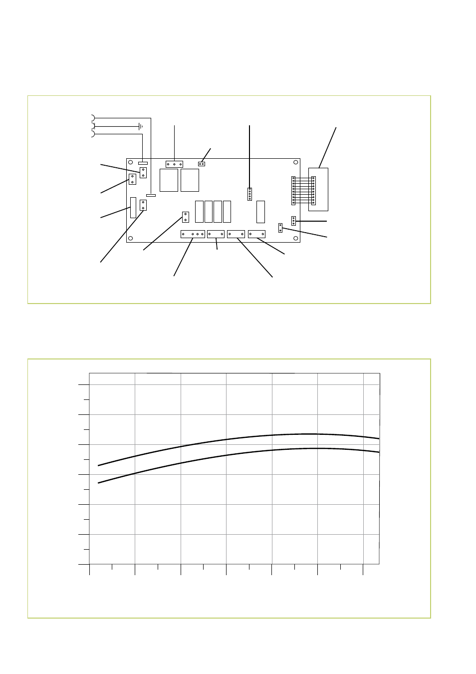
Electrical wiring diagram
L
N
F
,
3
15
A
230 V/1~/50Hz
Thermal fuse
Front
Heating element
Thermal fuse
Rear
Heating element
Heating element
Transformer
Output
Transformer
Input
Control panel
Thermostat
Heating element
Fan
Circulation air
Fan
Regeneration
circuit
Adsorption
rotor
Ioniser
Microswitch
Humidity sensor
Fin motor
5
10
15
20
25
30
2
4
6
8
10
12
Room temperature °C
Dehumidification capacity litr
e/day
80 % r.H.
60 % r.H
Capacity graph
Miniature fuse
Advertising