Remko wkf duo – REMKO WKF-120-180Duo Electrical wiring User Manual
Page 14
n
If the outdoor unit is installed on a roof, it and
the supporting structure must be earthed sepa-
rately (by connecting them to a lighting con-
ductor or foundation earth electrode).
n
With the series WKF 180 Duo, make sure that
on terminals L1(R), L2(S), L3(T) and N are
1
Fig. 8: Connection terminals - Outdoor unit
WKF 120 Duo
1: Power supply 230V/1~ /50Hz
Fig. 9: Connection terminals - Outdoor unit
WKF 180 Duo
NOTICE!
Make sure to connect the outdoor unit neutral
connector properly, otherwise the varistors on
the line-filter circuit board will be destroyed.
Temperature probes
n
The number of probes required can vary with
the type of system.
n
Observe the pertinent notes for the probe posi-
tion found in the hydraulic schematic.
n
The standard model includes an external probe
(S10) and an immersion probe (intended for
use as a custom hot-water probe (S08)).
n
If a solar plant is connected, a PT-1000 probe
(S01) must be used as a collector probe and a
PT-1000 probe (S02) as a bottom storage tank
probe.
n
All probes are to be connected to the indoor
unit switching cabinet in accordance with the
connection diagram.
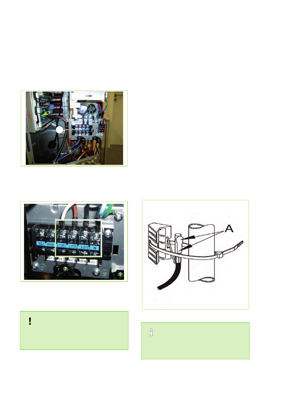
Contact probe
Contact probes can be mounted on the pipes, to
measure the heating-circuit temperatures, for
example.
n
The contact probe is fastened to a pipe with
the trapezoidal brackets and retaining strap
provided.
n
Clean the mounting point on the pipe. Subse-
quently a thermal compound (A) is applied and
the probe is fixed in position.
Fig. 10: Fastening the contact probe in place
If the sensor cables are too short, they can be
extended up to a maximum of 100m with wire
having a cross-section of 1.5 mm².
REMKO WKF Duo
14