RGBLink New Driver User Manual User Manual
Page 48
Advertising
New Driver User Manual 48
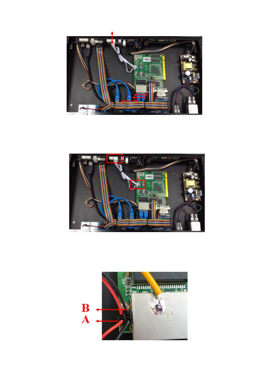
3. Connect the power line of sending card, (connect to the position marked LINSN
POW of the MCU board), take a 4 pin 2.54 mm pitch cable, and connect referring to
the following figure:
4. Connect the signal and power indicator light cable of sending card, take each 2 red
and black lines, and connect 2 black lines to the end of MCU board (Part B), and connect
2 red lines near the edge of the MCU board (Part A). Please refer to the following figure:
Advertising
This manual is related to the following products: