RGBLink New Driver User Manual User Manual
Page 49
Advertising
New Driver User Manual 49
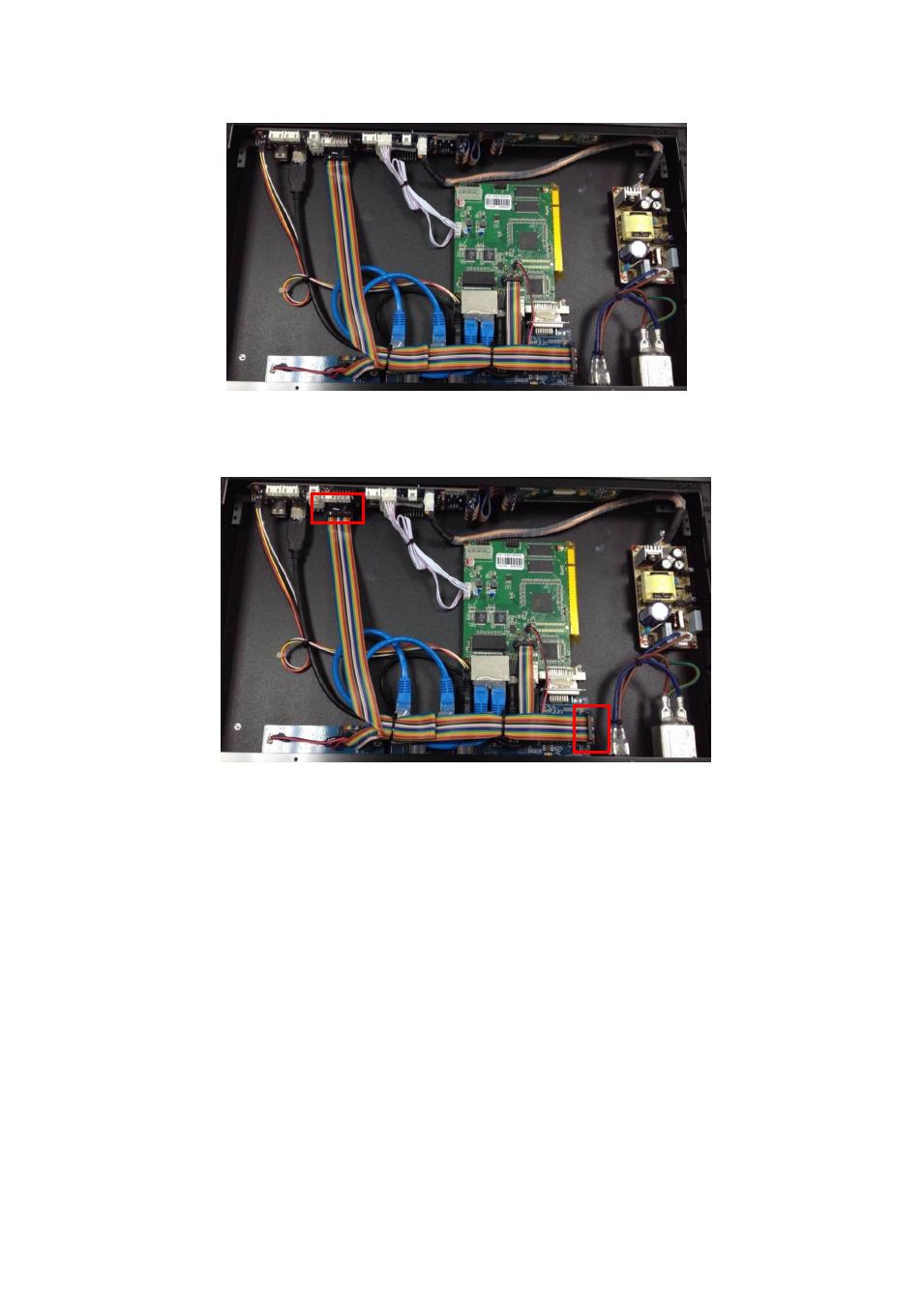
5. Connect (NEW DRIVER 2)-MCU board to (NEW DRIVER 2)-CON board with
2*8IDC line. Please refer to the following figure for more detailed connections:
6. Dispensing on each screw, and heat glue on each connection joints.
7. Finishing and binding the cables
.
8. After it has been confirmed correct, cover the front panel, and fixed by 6 pieces of
3*5 black flat head screws, as shown in the figure below:
Advertising
This manual is related to the following products: