Step 8. install and wire the decoder – SoundTraxx DSD-150/DSX Owners Manual User Manual
Page 14
14
Digital Sound Decoder Owner's Manual
to provide flexibility. If the wire is too short, it will rub against the synchronizer disk with excess force causing
premature wear and possible binding.
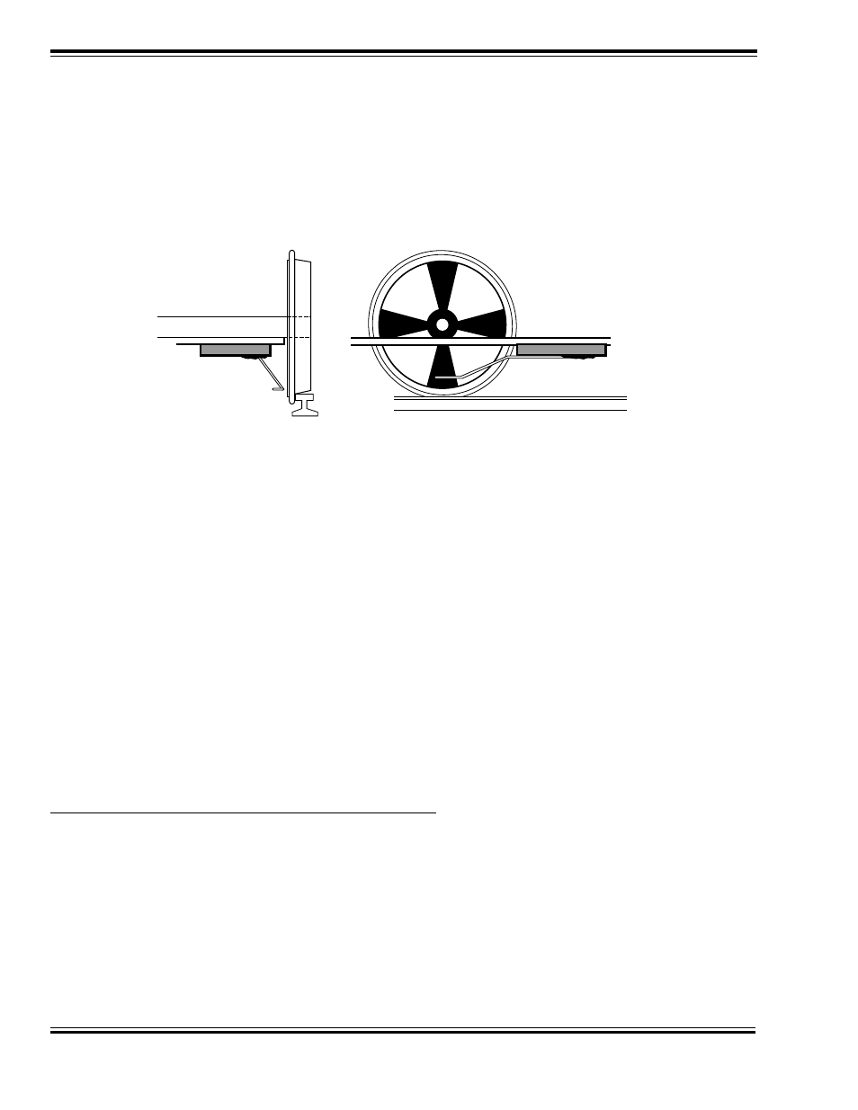
Temporarily mount the insulated side of the wiper base to the locomotive frame such that the wiper end barely rubs
against the synchronizer disk and does not touch any other part of the locomotive. Referring to Figure 8, adjust the
spring wire so that the contact point is centered directly below the axle and its plane is parallel with the top of the rail.
Once the wiper has been properly adjusted, move the wiper base until the spring wire is deflected by about 1/32" to
1/16" and secure the base in place with epoxy.
Figure 8 - Contact Wiper Alignment
Step 8. Install and Wire the Decoder
Begin by securing the decoder in place using double sided foam tape. Temporarily refit the body shell to ensure that
adequate clearance still exists.
When wiring the decoder, trim all wires to reduce unnecessary lead length. This will not only give your installation a
neater appearance but also prevent wires from interfering with the drive mechanism and getting pinched between the
frame and body shell.
To ensure long-term reliability, solder all connections and insulate with heat shrinkable tubing. Throttle Up! has heat
shrink tubing available for this purpose, Item no. 810036.
A separate connector should be used for the cam switch (if used) and wired to a P.N. 810058, single-pin connector.
It is also recommended that the female end of all connectors be wired to the decoder side of the harness. If the
connector becomes unplugged, it is less likely for the female end to inadvertently come in contact with a potentially
harmful electrical signal.
Motor and Power Connections
The DSD wires uses two wire harnesses color-coded per the NMRA Standard:
POWER, MOTOR AND LIGHTS (9-Pin Connector Pin-outs)
1
GREEN
F1 Power Sink
2
RED
Right Hand Rail Power Pickup
3
ORANGE
Motor (+) Terminal
4
BLUE
Function Common (+Raw)
5
WHITE
Headlight Power Sink
6
YELLOW
Backup Light Power Sink
7
GREY
Motor (-) Terminal
8
BLACK
Left Hand Rail Power Pickup
9
BROWN
F5 Power Sink