SoundTraxx DSD-150/DSX Owners Manual User Manual
Page 15
Digital Sound Decoder Owner's Manual
15
SPEAKER AND CAM (3-Pin Connector Pin-outs)
10
PURPLE
Speaker (-)
11
BROWN
Cam Input
12
PURPLE
Speaker (+)
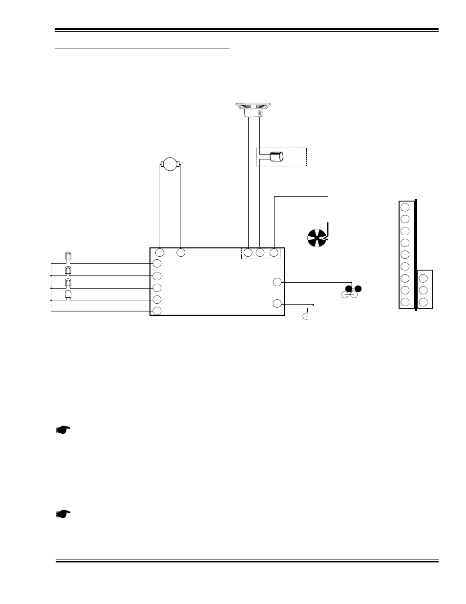
Figure 9 - Master Wiring Diagram
Referring to the master wiring diagram (Figure 9), begin with the power connection.
1.
Connect the decoder’s RED wire to the right hand rail power pickup (typically the locomotive frame).
2.
Connect the decoder’s BLACK wire to the left hand rail power pickup (typically the tender pickup)
3.
Connect the decoder’s orange wire to the motor’s (+) brush terminal.
4.
Connect the decoder’s gray wire to the motor’s (-) brush terminal.
BE ABSOLUTELY SURE THAT THE CONNECTIONS TO THE MOTOR ARE ISOLATED FROM EVERY-
THING OTHER THAN THE DECODER CONNECTIONS DESCRIBED ABOVE, AND MAKE SURE THERE
ARE NO SHORT CIRCUITS.
Speaker Connections
5.
Connect the decoder’s PURPLE wires to the plus and minus terminals on the speaker. If you have installed
multiple speakers, make sure they are phased properly, i.e., positive lead to positive lead and minus lead to
minus lead of each speaker.
A 100µf, 16V capacitor must be wired in series with the speaker (+) wire (pin 12) for steam DSDs. Use either
a 47uF or 100uF, 16V capacitor for the diesel DSDs. The positive (+) lead of the capacitor should connect to
the DSD wire. The negative (-) capacitor lead should connect to the speaker as shown in Figure 9.
Gray
Red
Black
Orange
Speaker +
Speaker -
-
+
100
µ
F
16V
47-100
µ
F
16V
(Diesel)
Purple
Purple
Brown
Function Common
Brown
Headlight
Backup Light
Function 1 Output
Blue
Yellow
White
Green
Function 5 Output
8
2
11
12
10
7
3
9
6
5
1
4
Motor -
Motor +
Left-hand Rail Pickup
Right-hand Rail Pickup
Cam
9
8
7
6
5
4
3
2
1
10
11
12
DSD Pinouts
(end View)