Figure 41: dac configuration, Smt6040, Sundance simulink toolbox – Sundance SMT6040 User Manual
Page 46
Sundance Multiprocessor Technology Limited
Form : QCF32
SMT6040
“Sundance Simulink Toolbox”
Date : 6 July 2006
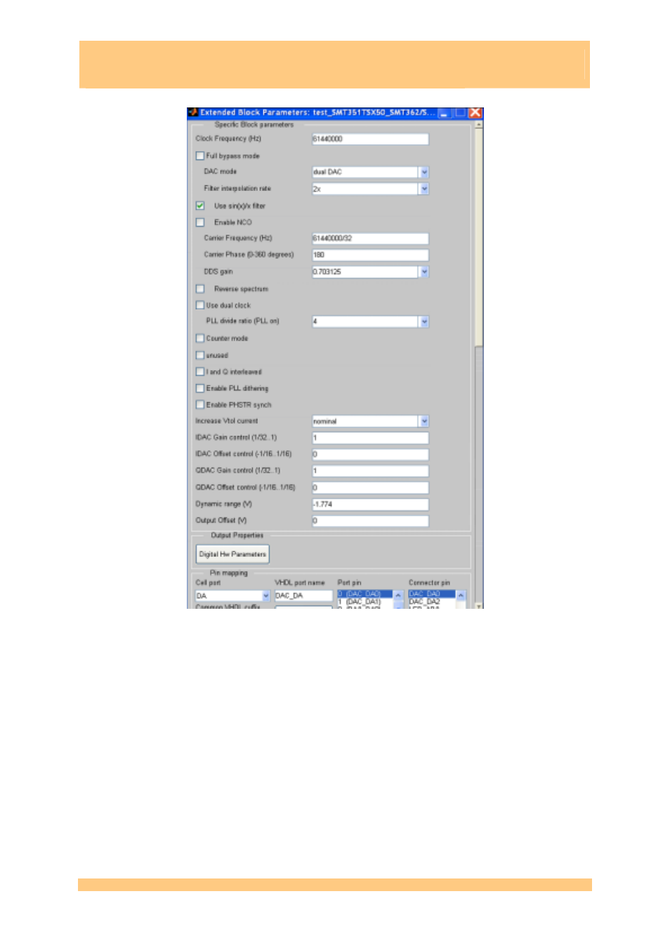
Figure 41: DAC configuration
The DAC part does the following:
o
It takes data coming from node1 via comport.
o
Demux data into two individual scalar channels.
o
Oversample both signals at 61,440,000 samples/s, as required by the DAC.
o
Generate a 61,440,000/8 Hz = 7.68 MHz sinewave.
o
Sum input signals to the sinewave.
o
Send both signals to the DAC, which is configured as in Figure 41, to operate as a normal
two independent channels DAC.
o
Output signals via the AC coupling to the coax connectors. During simulation, the analog
outputs are visible on the dual-channel scope present in the root model.
The ADC part does the following:
SMT6040 - “Sundance Simulink Toolbox”
Last Edited: 08/01/2010 15.42
Page 46 of 53