Figure 1: top view of the smt8101 – Sundance SMT8101 User Manual
Page 11
Advertising
Version 1.3
Page 11 of 16
SMT8101 User Manual
4 – Connect SHBA on the SMT395-VP to SHBA on the SMT338-VP via the SMT516.
5 – Connect SHBB on the SMT395-VP to SHBB on the SMT338-VP via the SMT511
(SHB to SHB cable).
6 – Connect J2 and J3 (SMT381-VP) to an oscilloscope or other system of display
via MMBX-BNC cables.
7 – Place the carrier board in the host system and power up the PC and a fan to cool
down the system.
8 – Connect a signal (0.36 Volts peak-to-peak) to J1 and J2 (SMT391-VP).
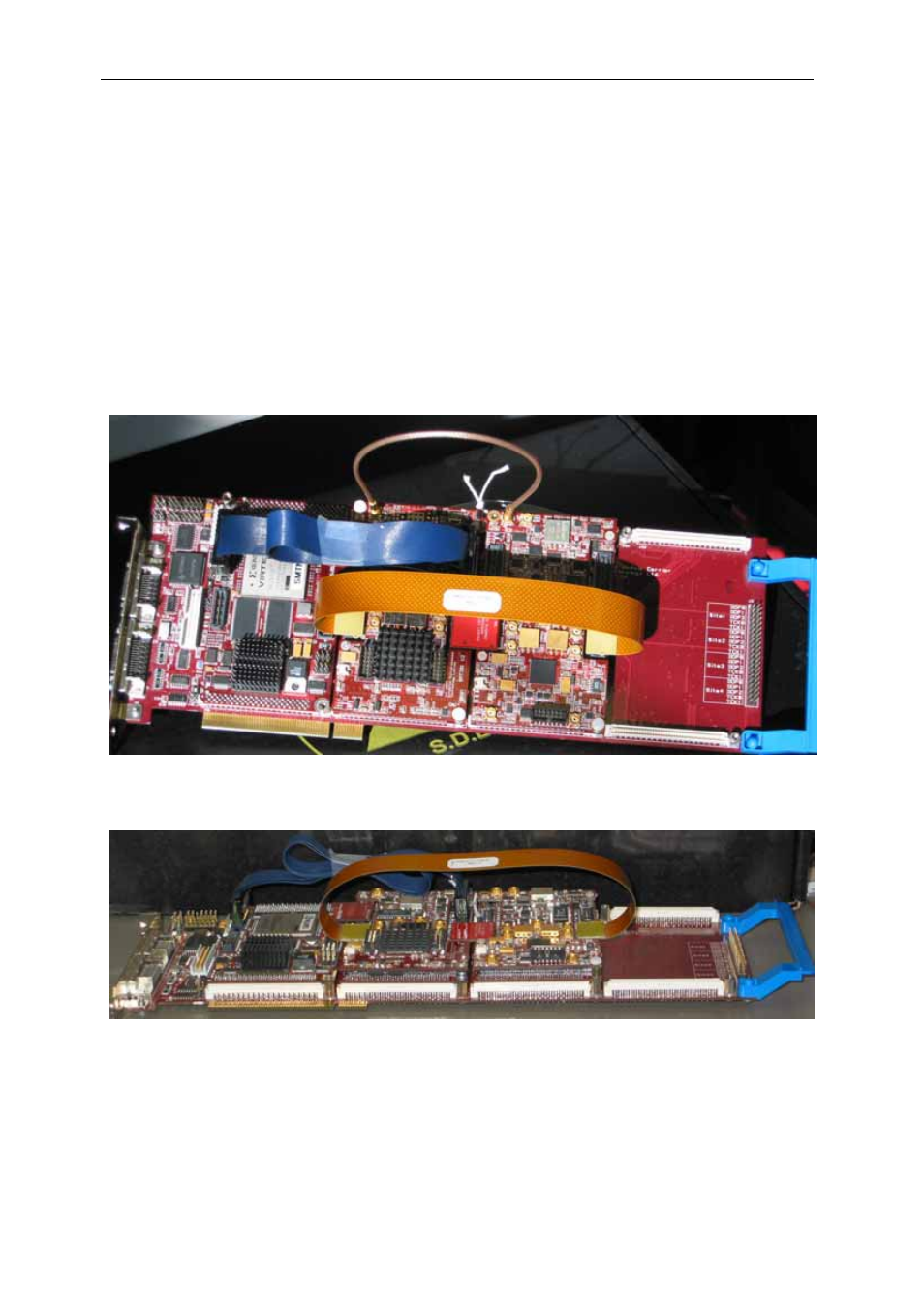
The following pictures show how connections are made at the top of the system:
Figure 1: top view of the SMT8101
Figure 2: the cable connections of the SMT8101 system
Advertising