TE Technology TC-36-25-RS232 User Manual
Page 20
2.4
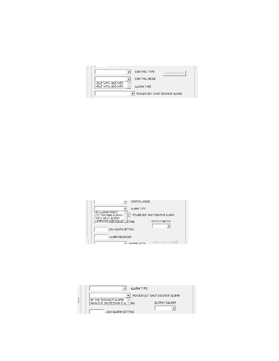
CONTROL MODE menu key:
HEAT WP1+ AND WP2- or HEAT WP2+ AND WP1-. This selection establishes the polarity for the heating mode of
the thermoelectric cooler. It allows you to reverse the current flow in the TE device without having to change the
wiring.
NOTE: For TE Technology’s standard products, the TE+ (red) wire should be attached to WP2 and the TE- (black)
wire should be attached to WP1 as shown in the “Controller Wiring Diagram.” The CONTROL MODE should then be
set to HEAT WP1+ and WP2-. Again though, do NOT connect the TE device at this time.
2.5
ALARM TYPE menu key:
a) NO ALARMS PICKED: no alarm condition will be monitored.
b) SET TRACKING ALARMS: allows an alarm to be set with respect to the set temperature. It will move accordingly
with a change of the temperature setting. This option can be used for a high alarm, low alarm, or both settings.
c) FIXED VALUE ALARMS: permits the setting of a fixed, absolute temperature either above or below the set point
temperature or both.
d) COMPUTER CONTROLLED ALARM: provides for user activation of the alarm relay via the computer software.
The “Expansion Connector Wiring Diagram” shows how customer-supplied LED’s can be installed to signal
various alarm conditions.
Associated with the ALARM TYPE configuration are the HIGH ALARM SETTING box, LOW ALARM SETTING box, and
the ALARM DEADBAND box. If an alarm type has been selected, enter the desired high and low temperature
values that will trigger an alarm condition. The ALARM DEADBAND option sets the hysteresis of the alarm values
from 0.1 degrees to 100 degrees.
2.6
POWER OUT SHUT DOWN IF ALARM menu key:
a) NO SHUT DOWN IF ALARM: controller will continue to supply power to the TE device regardless of alarm
condition.
b) MAIN OUT SHUTDOWN IF ALARM: shuts off power output to the TE device when an alarm condition exists.
20