A line out jacks, B digital out jack, C system control jack – Teac PD-H600 User Manual
Page 9: D system control selector switch, E signal gnd terminal, F ac inlet
9
ENGLISH
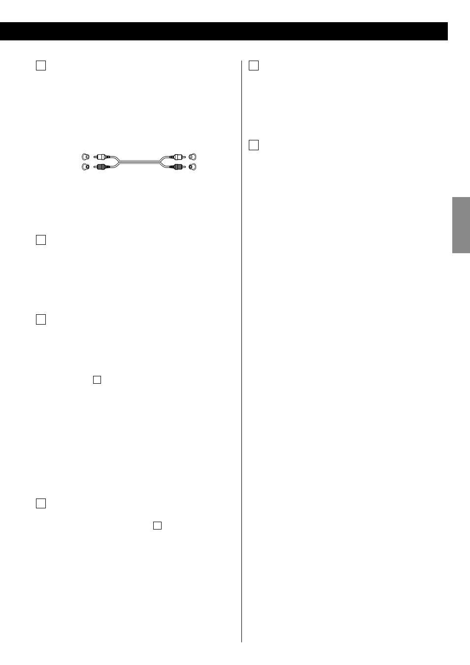
A LINE OUT jacks
These jacks transmit an analog 2-channel audio signal. Connect
them to the CD jacks of a receiver or an amplifier with the
provided RCA cables.
< Make sure to connect the cables as follows:
White plug q White jack (L: left channel)
Red plug q Red jack (R: right channel)
< Be sure to insert each plug securely. To prevent hum and noise,
avoid bundling the signal interconnection cables together with
the AC power cord or speaker cables.
B DIGITAL OUT jack
Connect it to a digital coaxial input terminal of a digital
apparatus such as a CD recorder with a commercially-available
digital coaxial cable.
< Make sure that the cable is firmly inserted.
C SYSTEM CONTROL jack
If you have TEAC AG-H600 series receiver, convenient system
control functions are available.
Connect it to the SYSTEM CONTROL jack on the AG-H600 series
receiver with the provided system control connection cord.
Then set the SYSTEM CONTROL SELECTOR switch on this unit to
“SYSTEM”. (See
D
.)
Available system control functions are as follows:
N When you turn on or standby the AG-H600 series receiver
using the remote control unit (RC-1181) of the receiver, this
unit is also turned on or standby synchronously.
N When you change the source from CD to another on
AG-H600 series receiver, playback stops and display turns off
on this unit.
Refer also to the manual of the AG-H600 series receiver.
D SYSTEM CONTROL SELECTOR switch
When you want to use the system control functions, connect
the SYSTEM CONTROL jacks (see
C
), and set the switch to
“SYSTEM”.
< The STANDBY/ON button on the remote control unit of this unit
does not work while the switch is set to “SYSTEM”.
< When you do not use the system control functions or do not
have a AG-H600 series receiver, set the switch to “SINGLE“.
Otherwise, you cannot turn on or standby the unit.
E SIGNAL GND terminal
Connect the signal ground of other components using a
commercially available jacketed cable (PVC-covered cable or
others).
< Note that this is NOT an electrical safety ground (earth).
F AC Inlet
Use only the supplied power cord.
< Use of other power cord may result in fire or electric shock.
< Unplug the power cord when you are not going to use the unit
for an extended period of time.
White (L)
Red (R)
White (L)
Red (R)