Tri Tool 201BA Beveler User Manual
Page 14
14
TRI TOOL INC.
92-0631 : Orig. 960119
NOTE:
CAUTION:
CAUTION:
WARNING:
Select the Tool Bit(s) required to machine the pipe to the configuration desired.
Refer to the section ‘Tool Bits’ for the Tool Bit selection chart.
Use of dull or improperly designed Tool Bits or Tool Bits not manufactured by
TRI TOOL Inc. may result in poor performance and may constitute abuse of
this machine and therefore voids the TRI TOOL Inc. factory warranty.
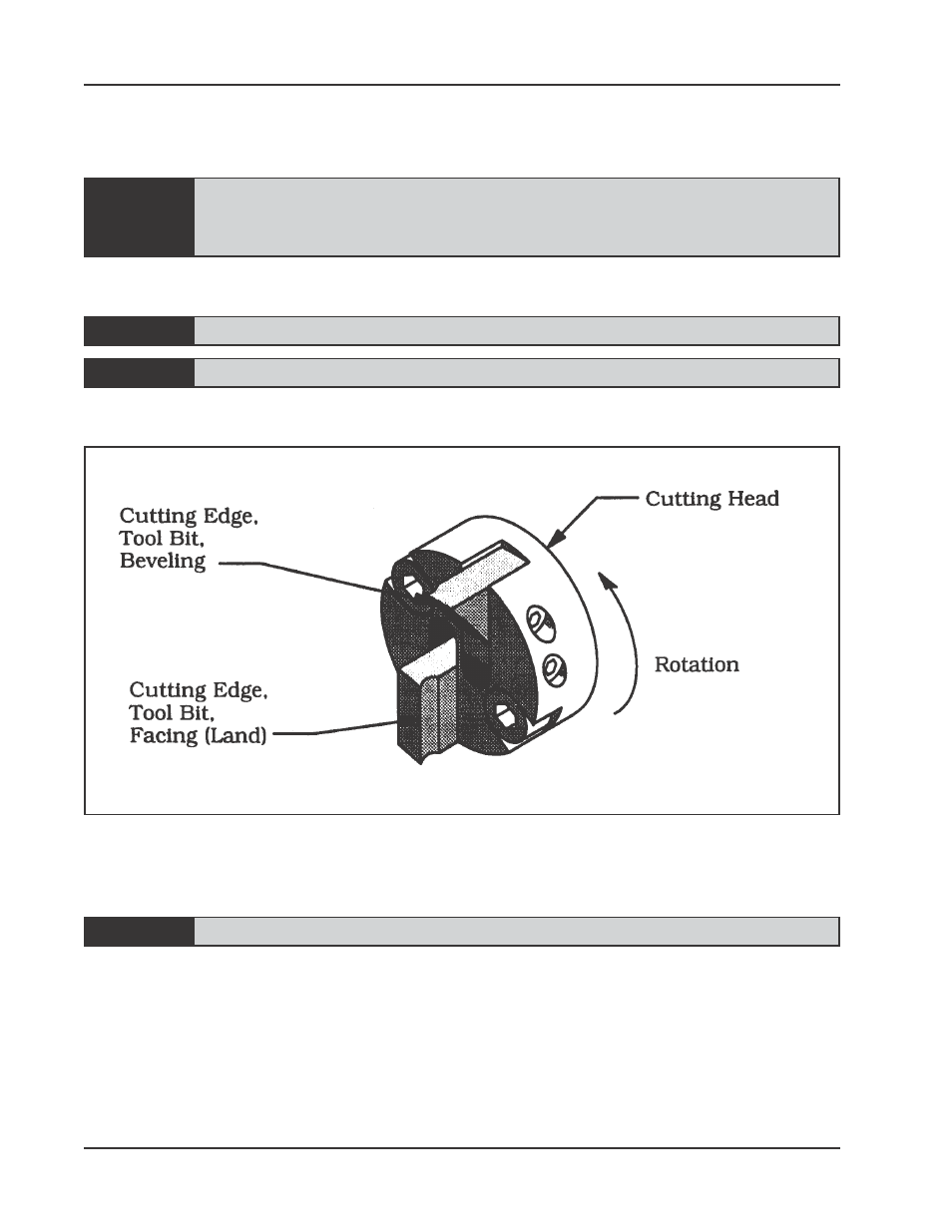
Insert the Tool Bit(s) into the Slot(s) in the Cutting Head.
The cutting edge of the Tool Bit(s) must be located on the radial centerline.
Make sure that there are not any tooll bits installed backwards.
Make sure that there is a clearance between the Tool Bit(s) and the Saddles.
Tool Bit Positioning
Tighten the Set Screws to secure the Tool Bit(s) to the Cutting Head.
Attach the proper air supply line to the Model 201BA.
Check that the filter/regulator/lubricator (FRL) is installed and set properly.
Depress the Air Motor Trigger.
Adjust the cutting speed by rotating the Flow Valve at the air connection. Refer to
the section ‘Cutting Speeds’ for recommended cutting speeds.
Rotate the Feed Handle clockwise to bring the Tool Bit(s) and pipe or tube closer
together.