Installation – Tri Tool 224B ID Tracking Module User Manual
Page 10
10
TRI TOOL INC.
92-0834 : Orig. 0990603
NOTE:
INSTALLATION
ATTACHING THE MODEL 224B ID TRACKING MODULE TO THE 224B
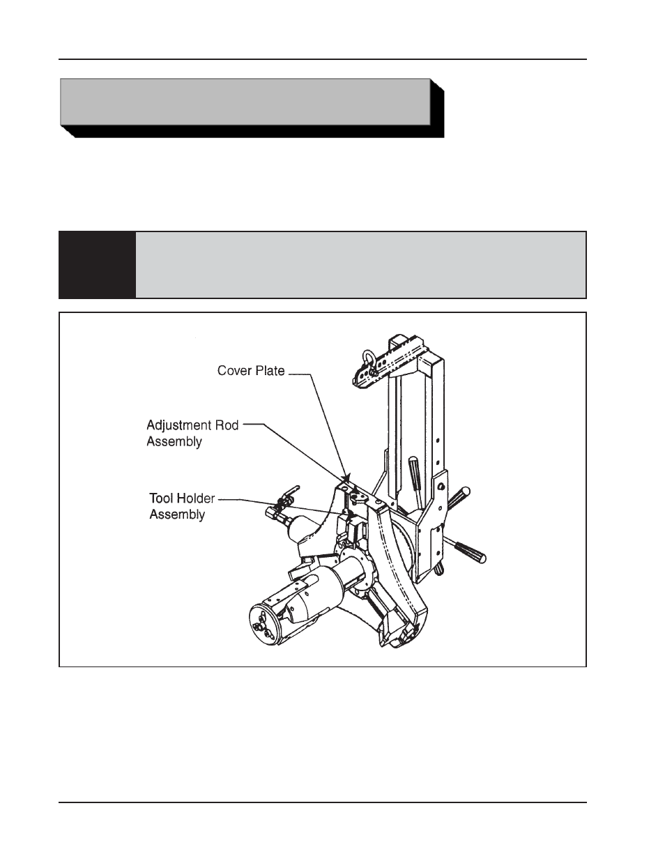
Remove the Counterbore, Tool Holder Assembly, Adjustment Rod Assembly and the
Cover Plate from the Model 224B Machine.
The bevel tool module and the facing tool module do not have to be removed
from the Model 224B while the ID Tracking Module is in use. These two modules
help balance the Headstock of the 224B. However, the tool bits, if any, should be
removed from these modules to avoid injuries.
Tool Configuration Prior to ID Tracking Module Installation
Install the Plate Assembly, Adapter (P/N 24-1722) onto Main Plate (flat), secure in
place with retaining cap screws.
Slide the ID Tracking Module into the “T” slots on the Adapter Plate Assembly and let it
slide to the end of the “T” slots (minimum cutting diameter).
Secure the module with the (6) cap screws on the base plate.