Operation, Status indicators, Aco switch/indicator – Verilink 1061 T1 Multicast (34-00268) Product Manual User Manual
Page 15: Force switch/indicators, Activity indicators, Operation -1
Operation 4-1
1061 Multicast Card
4. Operation
This chapter describes the operating features of the 1061
including LED indicators and option switches.
Status Indicators
There are two status indicators located on the top of the
front panel.
Green
Illuminates when the unit is powered.
Red
Illuminates when an alarm exceeds thresholds or
there is a unit failure.
ACO Switch/Indicator
The ACO switch controls the alarm relay circuitry. When
the switch is On (toggled to the left), the circuitry is deacti-
vated, however, the alarm indicator still functions normally.
The amber alarm cutoff (ACO) indicator illuminates when
the alarm relay contacts are forced to the No Alarms condi-
tion (ACO switch is On).
Force Switch/Indicators
The Force selector switch forces the input to either the A
input (toggle left) or B input (toggle right). NMS commands
will not override this switch. When not in use, the switch
should be placed in the center (N-normal).
The amber Force indicator illuminates when the Force
Select switch is in either the A or B position.
The green A and B indicators illuminate indicating which
input (A or B) is being broadcast to the ports. If both ports
have input, only the selected port’s indicator illuminates.
Activity Indicators
The two red activity indicators located just above the SUPV
connector allow you to identify transmission flow in the
unit. The left light indicates supervisory port transmission.
The right light indicates NMS bus transmission.
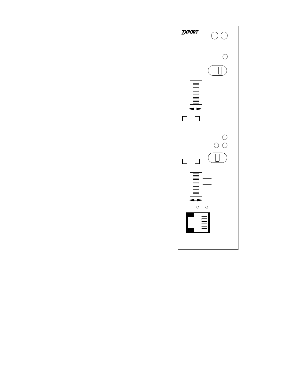
Figure 4-1 1061 Front Panel
T
R
A
N
S
P
O
R
T
®
1061
Multicast
ADDRESS
FORCE
ACO SW
ACO
STA-
A
B
N
A
B
B
A
NMS BR
S
U
P
V
SUPV BR
LSB
DUPLEX SEL
MSB