Configuration, Hardware configuration, Address – Verilink 1061 T1 Multicast (34-00268) Product Manual User Manual
Page 9: Nms bit rate, Supv bit rate, Duplex select, Configuration -1, Hardware configuration -1
Configuration 3-1
1061 Multicast Card
3. Configuration
The 1061 T1 Multicast can be configured through manual
switch settings (hardware) and/or through a VT100 terminal
connection (software).
All default options in this manual are underlined.
Hardware Configuration
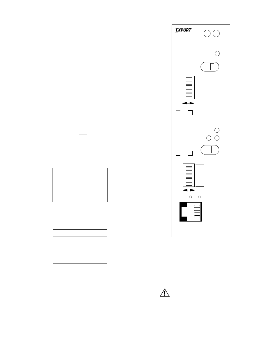
Hardware configuration is set using four toggle switches and
two dual in-line package (DIP) switches. These switches
allow you to configure simple applications. Refer to Figure
3-1 for switch locations. A removable configuration guide
(45-00117) is included in the back of this manual.
Address
This 8-pin switch (S1) sets the NMS address of the unit.
Valid addresses are 1 through 252. Address values 253
through 255 are reserved. Zero (or no channel) is the
default.
NMS Bit Rate
S2-1 and 2-2 set the NMS bit rate.
SUPV Bit Rate
S2-3 and S2-4 set the Supervisory port bit rate.
LSB
S2-5 sets the Least Significant Bit with respect to the duplex
select. Refer to Table 3-D for setting information.
Duplex Select
S2-6 and S2-7 select the channel (1-12) that is full duplexed
to the selected (A or B) input channel. No channel is
selected on zero. Table 3-D displays the switch settings for
the duplex select. The expansion settings (A EXPD, B
EXPD, and A/B EXPD) full duplex back to their respective
Table 3-B NMS Bit Rate
kbps
S2-1
S2-2
19.2 B
B
9.6
A
A
2.4
B
A
1.2
A
B
Table 3-C SUPV Bit Rate
kbps
S2-3
S2-4
19.2
B
B
9.6
A
A
2.4
B
A
1.2
A
B
T1 input lines. For example, the A EXPD setting full
duplexes the return feed back to the T1 A input line; the
B EXPD setting full duplexes the return feed back to
the T1 B input line; and the A/B EXPD setting full
duplexes the return feed back to the respective T1 A
and T1 B input lines.
When you bypass from an input
line to an expansion line, you
must have another 1061 unit connected
to the expand line. Failure to have a con-
nection will cause the signal to be inter-
rupted.
Figure 3-1 1061 Front Panel
T
R
A
N
S
P
O
R
T
®
1061
Multicast
ADDRESS
FORCE
D
ACO SW
ACO
STATUS
A
B
N
A
B
B
A
NMS BR
S
U
P
V
SUPV BR
LSB
DUPLEX SEL
MSB