Able of, Ontents – Verilink 400 (34-00222) Product Manual User Manual
Page 3
T
ABLE OF
C
ONTENTS
1. Introduction
.......................................................................... 4
Specifications ............................................................................................. 4
FCC Requirements .................................................................................... 5
Warranty .................................................................................................... 6
Ordering Information ................................................................................. 7
2. Installation
............................................................................ 8
Supplied Materials ..................................................................................... 8
Unit Configuration ..................................................................................... 8
Connections ...............................................................................................10
DDS Network Connection .............................................................. 10
V.35 and RS-232 Port Connection .................................................. 10
3. Operation
............................................................................ 13
Testing ...................................................................................................... 13
4. Customer Service
........................................................ 15
Telephone...................................................................................................15
E-mail ........................................................................................................15
World Wide Web........................................................................................15
3
14
V.54 Channel Loop: This loop is activated by the receipt of the V.54 loop com-
mand. This loop is unidirectional and returns the DSU receive data to the DSU trans-
mit data, and subsequently the DDS transmit data. Receive data is unaffected and
DSR and RLSD are forced Off.
Remote Channel Loop: This loop is activated by pressing the front panel switch to
the RL position. This starts an internal test by replacing the DSU’s transmitted data
with the V.35 activate code to the far end DSU equipment for the proper time period.
Then a test pattern is sent to verify the looped DDS DSU’s integrity. If the transmit-
ted pattern is received error free, the test lamp turns green. If errors are detected, the
test lamp turns red. Normal DSU operation may resume for DCE BERT testing.
Placing the switch in the NORM position transmits the V.54 deactivate code.
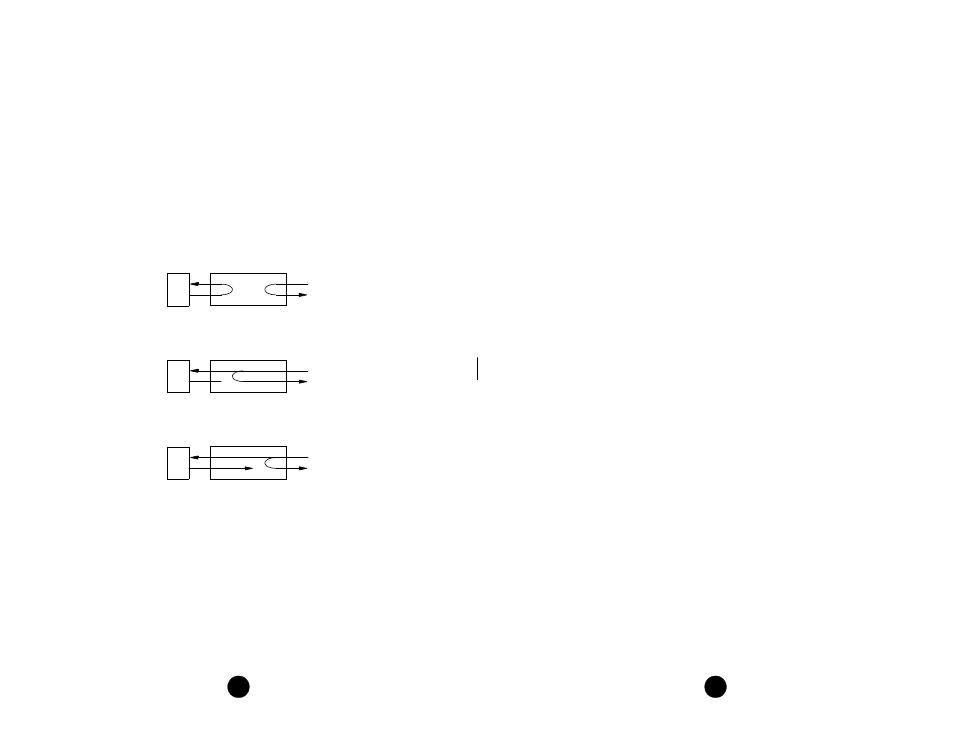
Looping Diagrams
DTE
NET
Local Loopback
DTE
NET
Remote Channel Loop
(V.54) and Data Set Loop
DTE
NET
Channel Loop (Mandatory Loop)