Introduction, Specifications, Testing – Verilink 400 (34-00222) Product Manual User Manual
Page 4: Productivity series 400
13
4
Productivity 400 DDS DSU/CSU
1.
Introduction
The TxPORT Productivity Series DDS 400 provides an economical solution to
access Digital Data Service. The 400 unit is fully compatible with AT&T TR62310,
the industry specification standard for DDS. This unit is designed for standalone
(table top) use, but may be rack mounted using the optional rack mount kit. See page
page 7 for ordering information.
The 400 rear panel has three interface connectors. An RJ-48C (8-pin) interface
allows connection to the network. The V.35 (34-pin) high speed port connector sup-
ports data rates of 2.4, 4.8, 9.6, and 56 kbps. An RS-232 (25-pin) interface is also
provided as a substitute for the V.35 interface.
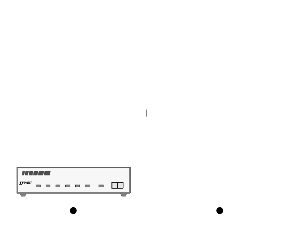
The 400 unit is configured through a rear panel DIP switch. LED indicators on the
front panel alert local personnel of the unit’s line, DTE, and test status. A test switch
activates a local loopback or initiates a remote loopback and pattern test.
A power cord on each unit provides 115 VAC operation. Primary and secondary
surge protection is provided on the network side (meeting UL 1459 requirements).
Each unit provides network ALBO circuitry. This network ALBO supports a receive
range of +1 dB down to -40 dB.
Specifications
Network Interface
Line Rate:
2.4, 4.8, 9.6, 19.2, 28, 38.4, 56, and 64 kbps
Line Code:
AMI
Line Impedance:
Balanced 135
Ω
Input Signal:
+1 to -40 dB (ALBO)
Output Signal:
3.0 V (±15%) base-peak into 135
Ω
,
1.5 V (±15%) at the 9.6 kbps line rate
Line Protection:
1000 V lightning, input/output
SD
RD
RTS
CTS
RLSD
LOOP
NORM
RL
LL
OOS
(BA)
(BB)
(CA)
(CB)
(CF)
TEST
DSU /CSU
PRODUCTIVITY
SERIES
400
T
R
A
N
S
P
O
R
T
®
the V.54 code). If errors are detected, the TEST LED will be red. The NORM posi-
tion deactivates the loop codes for normal operation. Refer to the Testing section on
page 4 for further information.
Testing
The front panel test switch is used as described in the following paragraphs. Three
types of loops are shown in the diagrams on page 14.
Local Loop: Each unit can initiate a local loop by placing the test switch in the
LOC position. The unit loops the signal from the customer equipment (DTE IN)
back to the customer equipment (DTE OUT). It also transmits the DTE data towards
the network.
Remote Channel Loop: Each unit can generate a far end remote channel loop by
placing the test switch in the RL position. The unit sends a V.35 loop code in the
assigned channels to the far end for two seconds followed by two seconds of all
ones, followed by DTE data. After four seconds, the far end should be looped.
In other words, this function starts an internal test by replacing the DSU’s transmit-
ted data with the V.54 activate code to the far end DSU equipment for the proper
time period. Then a test pattern is sent to verify the looped channel’s integrity. If the
transmitted pattern is received error free, the LED illuminates green. If any errors are
detected, the LED illuminates red. Normal DSU operation may resume at this time
for DCE BERT testing. Returning the test switch to NORM transmits the V.54 deac-
tivate code.
Normal (Unloop): When the test switch is moved from LOC back to NORM, the
local loopback is removed. When the test switch is moved from REM back to
NORM, the unit sends unloop messages to the far end unit for six seconds and the
remote loopback is removed.
The following paragraphs describe other loops that may be initiated on the 400 unit:
Channel Loop: This loop is activated by the reversal of the simplex, 20 mA sealing
current. This is a unidirectional loop that ignores the DSU transmit data and retrans-
mits the received DDS data. Receive data is unaffected and circuits CC and CF are
forced Off.
Data Set Loop: This loop is activated by the receipt of at least four consecutive
loop commands and remains looped as long as each third pattern byte is the loop
command. It returns to normal operation after at least four pattern bytes that are not
the loop command. This is a unidirectional loop that retransmits the DSU received
data on the DSU transmit data. Receive data is unaffected and circuits CC and CF
are Off.
Local Loop: This loop is activated by pressing the front panel switch to the LL
position. This loop is bidirectional and returns the DDS receive data to the DDS
transmit line and the DSU transmit data to the DSU receive data output.