Operation, Fcc requirements, Productivity series 400 – Verilink 400 (34-00222) Product Manual User Manual
Page 5
5
12
Power
AC Power:
115 VAC (± 10%), 150 mA maximum,
20 Watts, 73 BTU maximum
Connection:
5-foot power cord
Mechanical
Mounting:
Desktop, wall, or rack mount
Dimensions:
Height:
1.75 inches (4.45 cm)
Width:
6.8 inches (17.27 cm)
Depth:
10.5 inches (26.67 cm)
Weight:
2 pounds (0.91 kg)
Industry Standards
FCC Compliance:
Part 15 Subpart B, Class A, Part 68
U.S. Safety:
UL 1459
Canadian Safety:
CSA C22.2 No. 225-M90
IC:
CS03
Environmental
Operating Temp:
0° to 50° C (32° to 122°F)
Storage Temp:
-20° to 85° C (- 4° to 185°F)
Humidity:
95% max (non-condensing)
FCC Requirements
Changes or modifications to this unit not expressly approved by the party
responsible for compliance could void the user’s authority to operate the
equipment.
This device complies with Part 15 of the FCC rules. Operation is subject to the follow-
ing two conditions:
This device may not cause harmful interference.
2)
This device must accept any interference received, including interference that may
cause undesired operation.
This equipment has been tested and found to comply with the limits for a Class A digi-
tal device, pursuant to Part 15 of FCC Rules. These limits are designed to provide rea-
sonable protection against harmful interference when the equipment is operated in a
commercial environment. This equipment generates, uses, and can radiate radio fre-
quency energy and if not installed and used in accordance with the instruction manual,
may cause harmful interference to radio communications. Operation of this equipment
in a residential area is likely to cause harmful interference. The user will be required to
correct the interference at his own expense.
3.
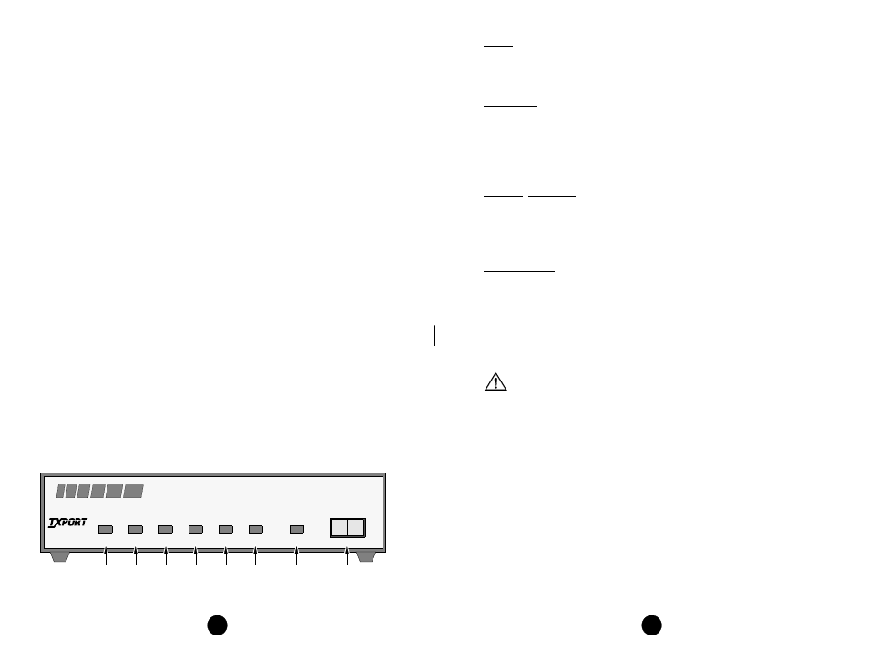
Operation
This chapter describes the front panel operation and test features of the TxPORT 400
DDS DSU/CSU. The unit is controlled manually using a front panel test switch and
rear panel DIP switches. Refer to page 8 for specific information concerning DIP
switch settings.
1)
OOS: This three color Out Of Service LED indicates the DDS loop receiver’s
operating status. Green indicates DDS signal at the receiver (either customer data or
zero suppression).
Amber indicates DDS signal is still present, but received data is
idle or out of service.
Red indicates an insufficient signal for the DDS receiver to
operate properly.
2)
SD: This green Send Data LED illuminates when the data lead is a mark and is
off when the data lead is a space. Therefore, the LED will vary from full intensity to
off depending on the relative number of marks and spaces.
3)
RD: This green Receive Data LED illuminates when the data lead is a mark and
is off when the data lead is a space. Therefore, the LED will vary from full intensity to
off depending on the relative number of marks and spaces.
4)
RTS: This green Request To Send’ LED illuminates when circuit CA is in the
On state at the DSU interface.
5)
CTS: This green Clear To Send LED illuminates when circuit CB is in the On
state at the DSU interface.
6)
RLSD: This green Receive Line Signal Detector LED illuminates when circuit
CF is in the On state at the DSU interface.
7)
LOOP/TEST: This amber LED remains illuminated if the unit is in a test mode,
either by manually depressing the loop switch or by receipt of a test command from the
facility. The LED turns red or green at the end of a V.54 test indicating the pass or fail
state of the BERT. Refer to the Testing section on page 4 for specific information.
8)
Test Switch: This 3-position switch is used as follows: The LL position places
the unit in a local loop mode. Data from the DTE is looped back to the DTE. Data from
the network is looped back to the network. The RL position initiates an automated V.54
remote loop and BERT sequence of assigned data channels. The TEST LED will be
green if the test is successful (the far end unit loops and returns the data error free with
SD
RD
RTS
CTS
RLSD
LOOP
NORM
RL
LL
OOS
(BA)
(BB)
(CA)
(CB)
(CF)
TEST
DSU/CSU
PRODUCTIVITY
SERIES
400
T
R
A
N
S
P
O
R
T
®
400 DDS Front Panel
7
5
4
3
2
1
6
8