Dte connection 2-4, Db-15 connection 2-4, Dte connection – Verilink 2100 (34-00187) Product Manual User Manual
Page 12: Db-15 connection
2-4
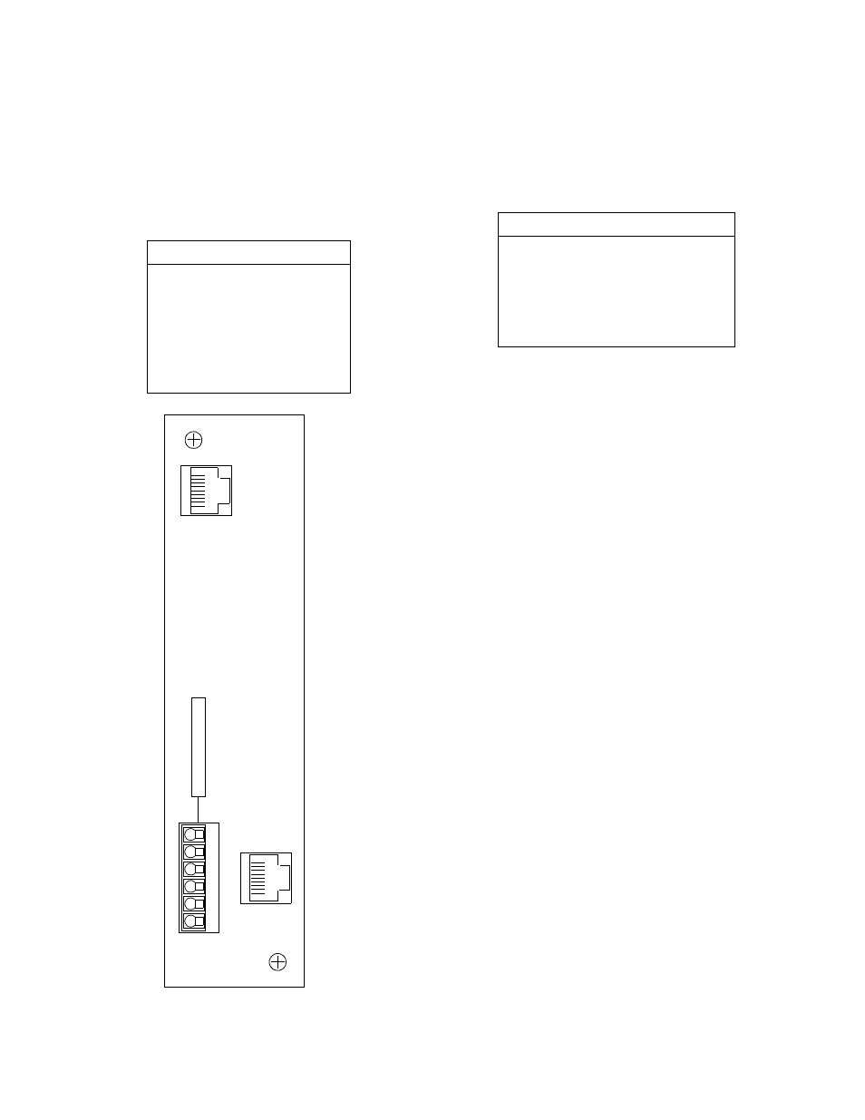
Installation
2100 CSU
DTE Connection
The DTE interface of the CSU is a DSX interface. The DTE
output level should be set as described in DSX Level on
page 2-3. The DTE physical interface for both the standal-
one unit (Figure 2 -4) and the chassis unit (Figure 2- 5 and
Figure 2-6) is a standard RJ-48C, 8-pin modular jack with
the pinout shown in Table 2-F.
DB-15 Connection
DB-15 connectors are optional for the DTE and network
interfaces. Refer to Optional Equipment on page 1-4 for
ordering information. The DB-15 pinout is shown in Table
2-G.
Table 2-F
DTE Interface Pinout
Pin
DTE Interface
1
Data Out
2
Data Out
3
Not Used
4
Data In
5
Data In
6
Not Used
7, 8
Chassis Ground
DTE
8
1
8
1
1
6
DB-15
(optional)
NET
Figure 2-4 2100 CSU Standalone Rear Panel
1 +V
2 GND
3 -V
4 FRM GND
5 ALM
6 ALM COM
DB-15
(optional)
Table 2-G
DB-15 DTE and Network Interface
Pinouts
Pin
DTE
NET
1
Data In
Data Out
2
Frame Ground
Frame Ground
3
Data Out
Data In
4
Frame Ground
Frame Ground
9
Data In
Data Out
11
Data Out
Data In