The main menu, Interpreting the main menu – Verilink Craft Interface (No Part Number) Product Manual User Manual
Page 3
Using the Craft Interface
Verilink Craft Interface
Craft-3
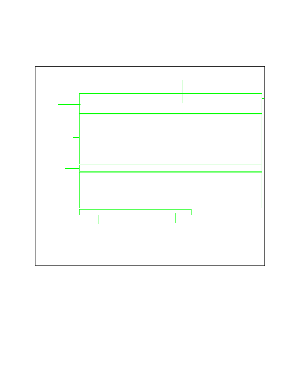
The Main Menu
Figure 2 defines the parts of the Main Menu.
Figure 2 The Main Menu
Interpreting the
Main Menu
The Main Menu shown in <HotSpot>Figure 2, provides:
•
a shelf/slot display showing card and shelf types and card
locations in each shelf
•
a key to the letters representing modules in the slots
•
a command list
•
node information
•
firmware revision number
-- VERILINK SCM CONTROLLER : FW Rev 1.18, Aug 24 1998 20:04:56 --
-- VERILINK SCM CONTROLLER : FW Rev 1.18, Aug 24 1998 20:04:56 --
-- VERILINK SCM CONTROLLER : FW Rev 1.18, Aug 24 1998 20:04:56 --
-- VERILINK SCM CONTROLLER : FW Rev 1.18, Aug 24 1998 20:04:56 --
Site name: SCM Tutorial Access level: 2
Site name: SCM Tutorial Access level: 2
Site name: SCM Tutorial Access level: 2
Site name: SCM Tutorial Access level: 2
Managing at NEAR end node [0.0.0.2] Node id: 122
Managing at NEAR end node [0.0.0.2] Node id: 122
Managing at NEAR end node [0.0.0.2] Node id: 122
Managing at NEAR end node [0.0.0.2] Node id: 122
<- SLOT ->
<- SLOT ->
<- SLOT ->
<- SLOT ->
SHELF 1 2 3 4 5 6 7 8 9 10 11 12 13
SHELF 1 2 3 4 5 6 7 8 9 10 11 12 13
SHELF 1 2 3 4 5 6 7 8 9 10 11 12 13
SHELF 1 2 3 4 5 6 7 8 9 10 11 12 13
0 - - - - - - - - - - - - -
0 - - - - - - - - - - - - -
0 - - - - - - - - - - - - -
0 - - - - - - - - - - - - -
1 M [*S] D Q Q I M H - - - - - -
1 M [*S] D Q Q I M H - - - - - -
1 M [*S] D Q Q I M H - - - - - -
1 M [*S] D Q Q I M H - - - - - -
2 - - - - - - - - - - - - -
2 - - - - - - - - - - - - -
2 - - - - - - - - - - - - -
2 - - - - - - - - - - - - -
3 - - - - - - - - - - - - -
3 - - - - - - - - - - - - -
3 - - - - - - - - - - - - -
3 - - - - - - - - - - - - -
4 - - - - - - - - - - - - -
4 - - - - - - - - - - - - -
4 - - - - - - - - - - - - -
4 - - - - - - - - - - - - -
KEY: D=QUAD D, I=IMUX, M=M13, Q=QUAD T1, S=SCM
KEY: D=QUAD D, I=IMUX, M=M13, Q=QUAD T1, S=SCM
KEY: D=QUAD D, I=IMUX, M=M13, Q=QUAD T1, S=SCM
KEY: D=QUAD D, I=IMUX, M=M13, Q=QUAD T1, S=SCM
S) shelf/slot O) administration
S) shelf/slot O) administration
S) shelf/slot O) administration
S) shelf/slot O) administration
C) configuration D) diagnostics
C) configuration D) diagnostics
C) configuration D) diagnostics
C) configuration D) diagnostics
P) performance/status A) alarm
P) performance/status A) alarm
P) performance/status A) alarm
P) performance/status A) alarm
B) circuit manager I) manufacturing info
B) circuit manager I) manufacturing info
B) circuit manager I) manufacturing info
B) circuit manager I) manufacturing info
X) logoff
X) logoff
X) logoff
X) logoff
A [0.0.0.2] [1,1] SCM >
A [0.0.0.2] [1,1] SCM >
A [0.0.0.2] [1,1] SCM >
A [0.0.0.2] [1,1] SCM >
Menu Heading Area
Shelf/Slot Map
Command List
Firmware Version and Date of Release
Access Level (1-4)
Node Address
Node Address (Not IP Address)
Data (Command) Entry Area
Module Key
Active SCM Master Designator
❷
❸
❶
❷
❸
❶
Asterisk indicates that the SCM is the Shelf Controller
Indicator for the type of shelf: M= Multi-line, D = Dual-line
Brackets around module letter ( [P] ) indicate current module selected