Operator’s manual, 5 operation – Watson-Marlow FC32 User Manual
Page 6
OPERATOR’s MANUAL
FC32
FC32 OM 1.02 EN
Version: 1.02
Page 6 of 10
5 Operation
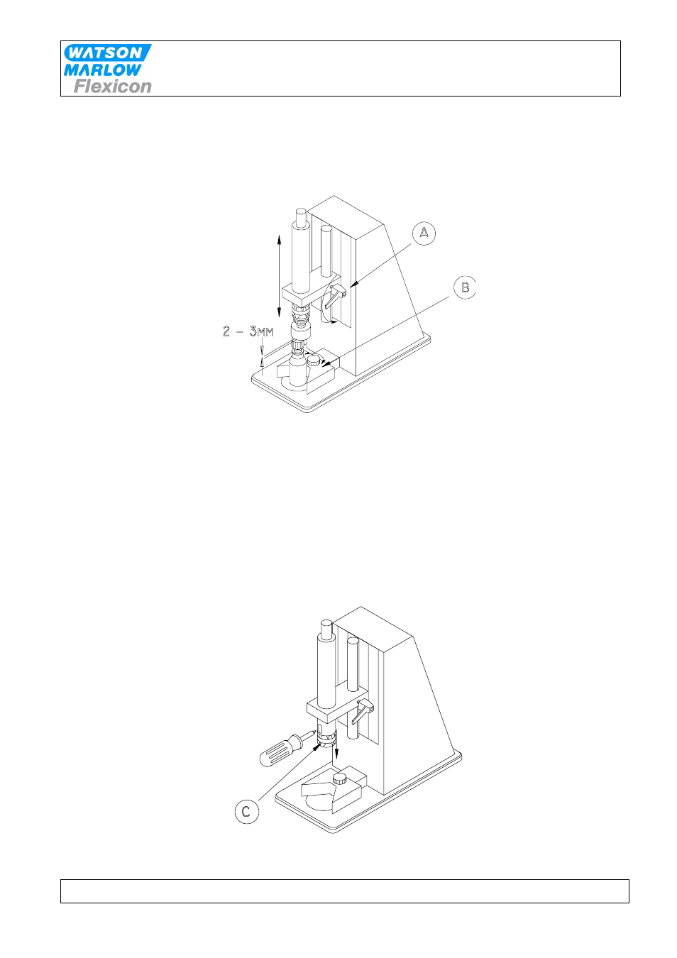
5.1 Adjusting the height
Fig. 5.1
When the power and air is connected, the screw unit with screw head is in the upper position. Place a
bottle with cap (the cap just pre screwed as during operation) on the foot of the machine. By
loosening the finger screw (A) the position of the screw unit can be adjusted. Make sure that the
screw head is just 2 - 3 mm above the cap. The bottle grip (B) must be adjusted, so the unit gets
activated, when the bottle is under the centre of the screw unit.
5.2 External torque adjustment
The clutch casing sleeve (C) is pushed down, and the screw head is rotated until the hole in the
adjustment lock plate is visible through the slot. The torque of the cap can then be increased by
inserting a Phillips screw driver and rotating it clockwise. Rotating the screw driver counter clockwise
will decrease the torque.
Fig. 5.2