Controller installation & wiring, Controller inputs and outputs, Technical guide vavbox controller 6 – WattMaster VAVBOX User Manual
Page 6: General, Controller mounting, Important wiring considerations, Figure 4: vavbox controller wiring, Airflow probe & sensor
Technical Guide
VAVBOX Controller
6
1
0
Locate In Supply Or
Discharge Duct
Near Zone Damper
Connect To Next VAVBOX
Controller Or WMVAV
Controller On Local
Communications Loop
24 VAC Transformer
Size For 6 VA
Maximum Load
Line Voltage
Connection To AUX
Terminal Is Only Required
When Sensor Is Specified
With Slide Adjust Option
Zone Actuator
Duct Supply
Or Discharge
Temperature
Sensor
Room Sensor
(See Note 2)
OVR
R
E
L
O
C
R
E
M
R
O
A
W
Hi
Lo
Airflow
Airflow Probe & Sensor
(For Pressure Independent Applications Only)
To Optional Relay
Expansion Board
CX6
SW1
U10
75176
EXP
ANSION
Q3
Q2
D3
VR1
7824
GND
R
SHLD
GND
GND
GND
GND
AUX2
AUX1
AUX2
AUX1
AUX
+VS
TMP
24VAC
GND
TMP
GND
AUX
TMP
T
24VAC
R17
R16
U7
C7
R15
POWER
R21
R35
YS101
562
REV
3
D4
R26
LD3
L1
SCAN REC
R12
C6
R1
1
TOKEN
NET
LD2
32
R14
R13
R100
LD1
C5
D1
K1
V2
V3
K2
D2
ACTUA
TO
R
R10
R9
PJ2
V1
C4
EPROM
VREF
ADJ
R23
C10
EWDOG
COMM
D7
CX10
R25
R28
T'STAT
U1
1
C15
R20
C1
1
R24
8
16
2
4
ADDRESS
ADD
1
U6
U5
R19
U9
CX9
R32
D5
C14
P.U.
R22
C13
R27
D5
RAM
C9
C8
80C55
2
CX5
PJ1
C3
R8
R7
R5
R6
R4
C2
C1
X1
U2
R1
R2
R3
CX2
Q1
16L8
R34
FLOW
U8
1
RN1
CX8
U4
R18
CX4
U3
CX3
U1
PA
L
CX1
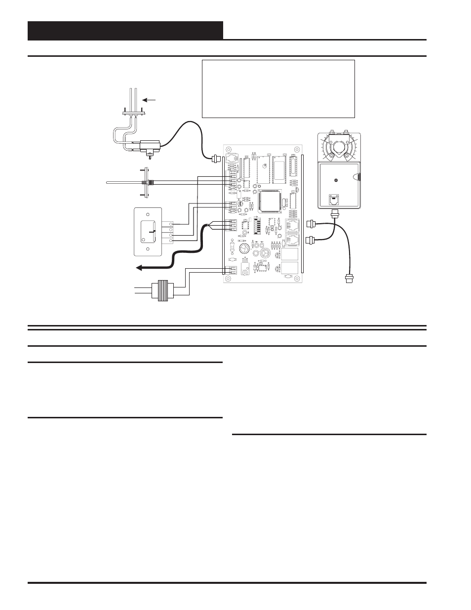
2.) A Duct Supply Air Temperature Sensor is not required when the VAVBOX
Controller is connected to an WMVAV Unit Controller board. A global Supply
Air temperature is broadcast by the WMVAV Unit Controller. The Supply Air
Temperature Sensor is required if the VAVBOX Controller is required to
operate as a “Stand Alone” controller. The Duct Sensor can also be placed on
the discharge side of the VAVBOX duct and used as a Discharge
Temperature Sensor to monitor VAVBOX discharge air temperature if desired.
This is normally used only if the VAV Terminal unit has heating capabilties.
1.) All wiring to be in accordance with local and national electrical codes
and specifications.
Notes:
Figure 4: VAVBOX Controller Wiring
Controller Installation & Wiring
General
Correct wiring of the VAVBOX controller is the most important factor
in the overall success of the controller installation process. The VAVBOX
controller wiring has been simplified by the use of modular connectors
and prefabricated modular cables.
Controller Mounting
If the Round Zone Dampers were purchased from WattMaster, the con-
troller and actuator are factory mounted and wired in the damper con-
trol enclosure. If your VAVBOX controllers are pressure independent,
an airflow probe and pressure sensor will also be factory mounted and
wired.
Most terminal unit manufacturers will offer the option of factory mount-
ing the WattMaster controls in their terminal units for an additional
charge. An installation worksheet and instructions are available for the
WattMaster VAVBOX controller package which can be shipped with
the VAVBOX control(s) to the terminal unit manufacturer to simplify
third party factory mounting and wiring of the controller.
When the VAVBOX controller is to be field mounted, it is important to
mount the controller in a location that is free from extreme high or low
temperatures, moisture, dust and dirt. The VAVBOX controller board
must be mounted within 10” of the damper actuator in order for the
actuator cable to extend between the controller and the actuator.
Be careful not to damage the electronic components when mounting
the controller. Remove the controller from its snap track mount. Mark
the control enclosure base using the snap track as a template. Drill pilot
holes in the enclosure base and secure the snap track to it using sheet
metal screws. Do not allow metal shavings to fall onto the circuit board.
Reattach the controller to the snap track. Mount the damper actuator to
the damper shaft following the instructions supplied with the damper
actuator.
Important Wiring Considerations
Please carefully read and apply the following information when wiring
the WMVAV controller. See Figure 4 for VAVBOX controller wiring
diagram.
1.
Size and wire the transformer per the instructions. Failure
to size the transformer and/or wire the transformer
correctly may cause the VAVBOX controllers to not
operate erratically or not at all. See
Figure 5 for wiring
and
transformer sizing information.
2.
If a Duct Sensor is to be connected, the minimum
wire size used should be 24 gauge.
3.
Do not pry on the connectors when connecting or
disconnecting the modular cables. Be sure to push in on the
connector release clip and then pull straight up.
Controller Inputs and Outputs