Westermo ODW-730-F2 User Manual
Page 15
15
6651-2255
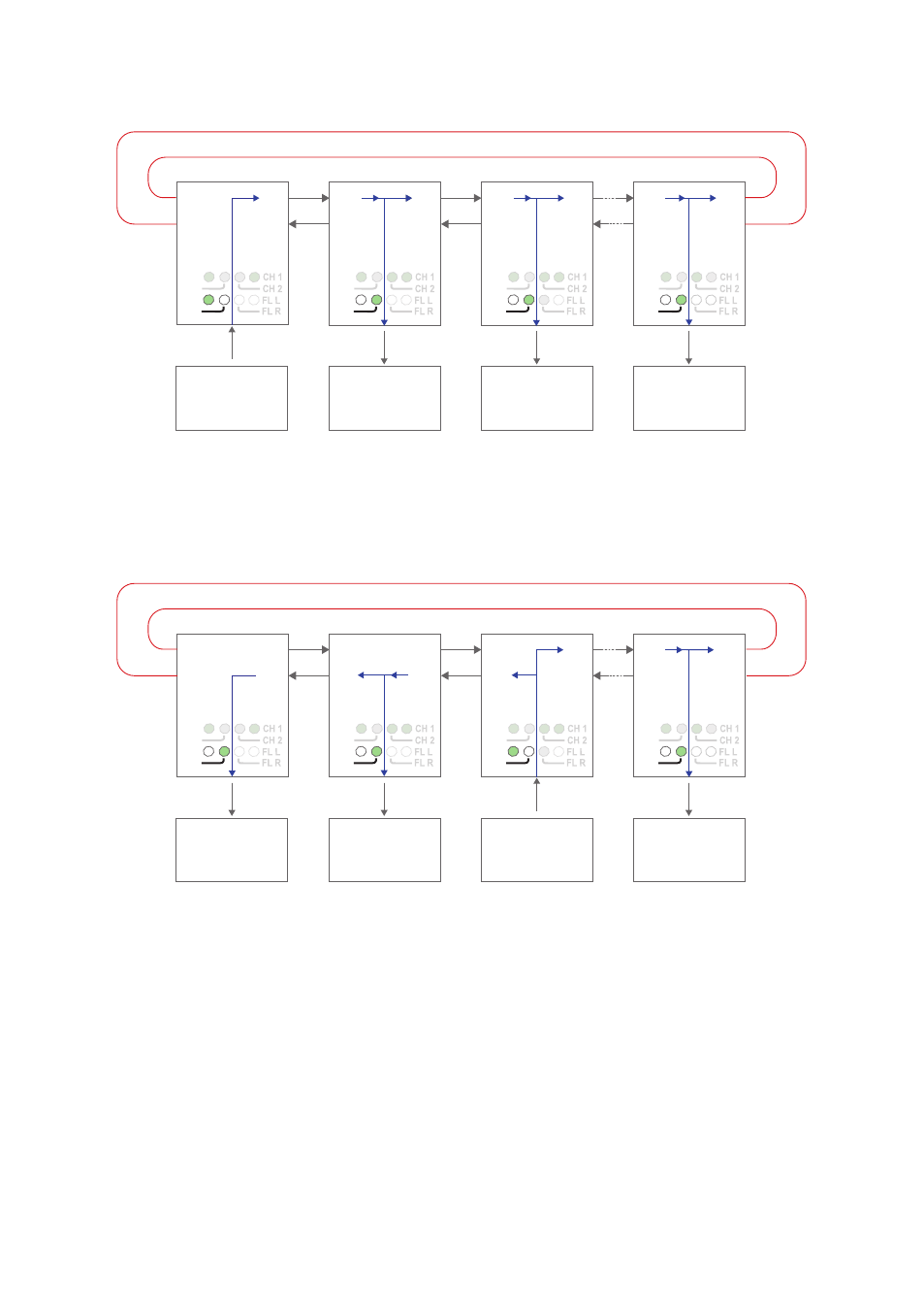
Data transport in redundant ring, Y-mode configuration
RX2
TX2
Device 1
Sending
Device 2
Receiving
Device 3
Receiving
Device n
Receiving
TX1
RX1
RX2
TX2
TX1
RX1
RX2
TX2
RS-485
RS-485
RS-485
Fibre
pair
Fibre
pair
Fibre
pair
Focal point
RS-485
TX1
RX1
RX2
TX2
TX1
RX1
PWR
FP
TD
RD
PWR
FP
TD
RD
PWR
FP
TD
RD
PWR
FP
TD
RD
Data from comminication device 1 is received at the ODW-730 RS-485 port (as indi-
cated by the TD LED), data bits are retimed according to the preset rate and sent out
on the optical fibre TX1. The next ODW-730 unit receives data at optical fibre RX2 (as
indicated by the RD LED), and data is sent out on the RS-485 port. Data is also repeated
out on TX1 on to the next ODW-730 unit.
RX2
TX2
Device 1
Receiving
Device 2
Receiving
Device 3
Sending
Device 4
Receiving
TX1
RX1
RX2
TX2
TX1
RX1
RX2
TX2
RS-485
RS-485
RS-485
Fibre
pair
Fibre
pair
Fibre
pair
Focal point
RS-485
TX1
RX1
RX2
TX2
TX1
RX1
PWR
FP
TD
RD
PWR
FP
TD
RD
PWR
FP
TD
RD
PWR
FP
TD
RD
Data from some other communication device, for example device 3, is processed in the
same way and sent out on both optical fibres TX1 and TX2. Notice that the Ring Focal
point never repeats incoming data.