Redundant ring, v-mode configuration, Prepare the fibre optical network – Westermo ODW-730-F2 User Manual
Page 17
17
6651-2255
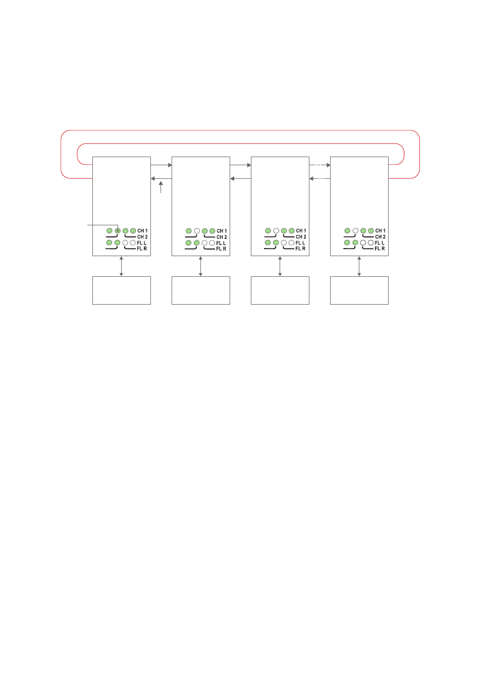
Redundant ring, V-mode configuration
In a redundant ring an extra fibre pair is used. This extra fibre pair is used to carry data
if one of the other fibre pairs breaks. In V-mode mode an ODW-730 network will behave
as a 4-wire bus. Where the first ODW-730 (leftmost in the picture below) will able to
communicate in full duplex with any other unit, but other units are incapable of commu-
nicating with each other.
RX2
TX2
Focal point
S1:8 ON
S2:2 ON
S2:3 ON
Ring member
S1:8 ON
S2:2 ON
S2:3 OFF
Ring member
S1:8 ON
S2:2 ON
S2:3 OFF
Ring member
S1:8 ON
S2:2 ON
S2:3 OFF
Device 1
Communicates
with all other devices
Device 2
Communicates
with device 1 only
Redundant fibre pair. Not used under normal operation.
Device 3
Communicates
with device 1 only
Device n
Communicates
with device 1 only
TX1
RX1
RX2
TX2
TX1
RX1
RX2
TX2
RS-485
RS-485
RS-485
Fibre
pair
Fibre
pair
Fibre
pair
Fibre
pair
used
to
carry
data
FP LED
is on to
indicate
focal point
RS-485
TX1
RX1
RX2
TX2
TX1
RX1
PWR
FP
TD
RD
PWR
FP
TD
RD
PWR
FP
TD
RD
PWR
FP
TD
RD
Prepare the fibre optical network
• Configure all ODW-730 units for the correct speed and data format using DIP-
switches S1:1 – S1:7.
• Select RS-485 2 wire and 4-wire mode using DIP-switch S2:1 (OFF = 2-wire,
ON = 4-wire).
• Enable the RS-485 termination / fail-safe if required using DIP-switches S3:1 – S3:4
(S3:1 and S3:2 = 4-wire termination, S3:3 and S3:4 = 2-wire termination)
• Set DIP-switch S1:8 in the ON position (V-mode) on all ODW-730 units.
• Set DIP-switch S2:2 in the ON position (redundant ring) on all ODW-730 units.
• One, and only one, of the ODW-730 units must be configured as a Ring Focal Point by
setting DIP-switch S2:3 to the ON position. (The Ring Focal Point acts as a logical end
point in the optical fibre ring, thus forming a bus type of structure)
• Set DIP-switch S2:6 as desired. See page 34 “Status port” for more information.
• Verify that DIP-switches S2:4, S2:5 and S2:8 are set in the OFF position.
• Connect the fibre pairs between the units. Always connect CH 1 from one unit to
CH 2 on the next unit as shown in the picture above.
• Connect the power supply to all units and verify that all fibre links become active.
(CH 1 and CH 2 LED’s are on, FL L and FL R LED’s are off).
• Connect the communication devices to the corresponding ODW-730 unit.
• The network is now up and running.
Note: In an ODW-730 fibre optic network there will be some additional processing
delays that do not exist in an electrical bus. It is possible that the application must be