Westermo FD-40 User Manual
Page 12
12
6630-2242
6.3 Indicators
6.3.1 LED indicators
6.4 Configuration
Most of the FD-40 settings have to be carried out by FD-Tool, a PC based configuration
software, either on-line or off-line. Only RS-232 or RS-485 transfer settings will be set by
DIP switches.
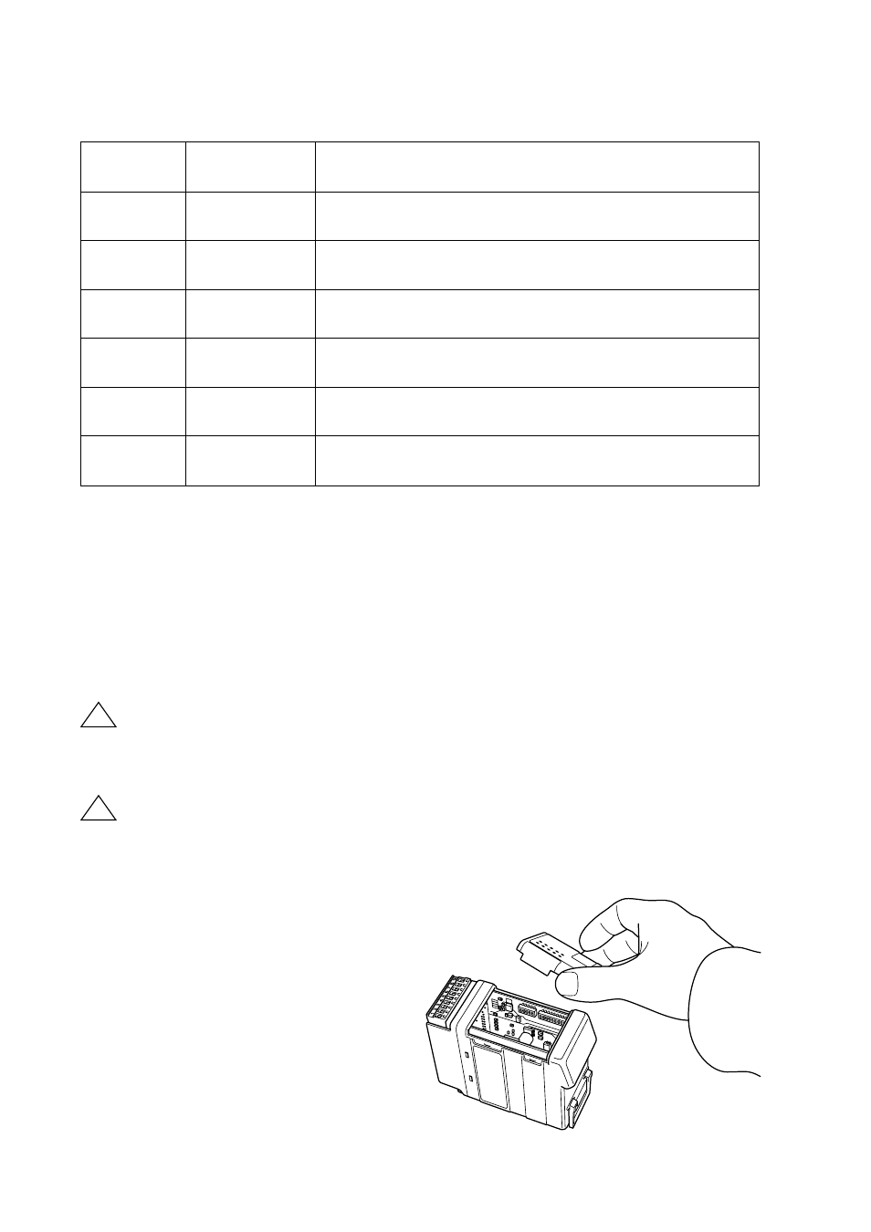
6.4.1 DIP switch settings
DIP-switches are accessible under the lid on top of the unit.
Warning!
Prevent damage to internal electronics from electrostatic discharges
(ESD)
by discharging your body to a grounding point (e.g. use of wrist
strap), before the lid on top of the modem is removed.
Warning!
Do not open connected equipment.
Prevent access to hazardous voltages by disconnecting the unit from
AC/DC mains supply and all other electrical connections.
NOTE
The change of DIP switch settings are valid only after a power on.
!
!
PWR
LED on
In service
LED off
Out of service
BA
LED on
PROFIBUS DP active
LED off
PROFIBUS DP inactive
CONF
LED on
Configuration mode
LED off
Normal operation mode
TD
LED on
Transmit serial (RS-232/485) data
LED off
–
RD
LED on
Receive serial (RS-232/485) data
LED off
–
RTS
LED on
Request To Send (RTS) set
LED off
–
CTS
LED on
Clear To Send (CTS) received active
LED off
–