4 fibre channel – Westermo LR-11 User Manual
Page 13
13
6608-2211
4 FIBRE CHANNEL
4.1 Introduction
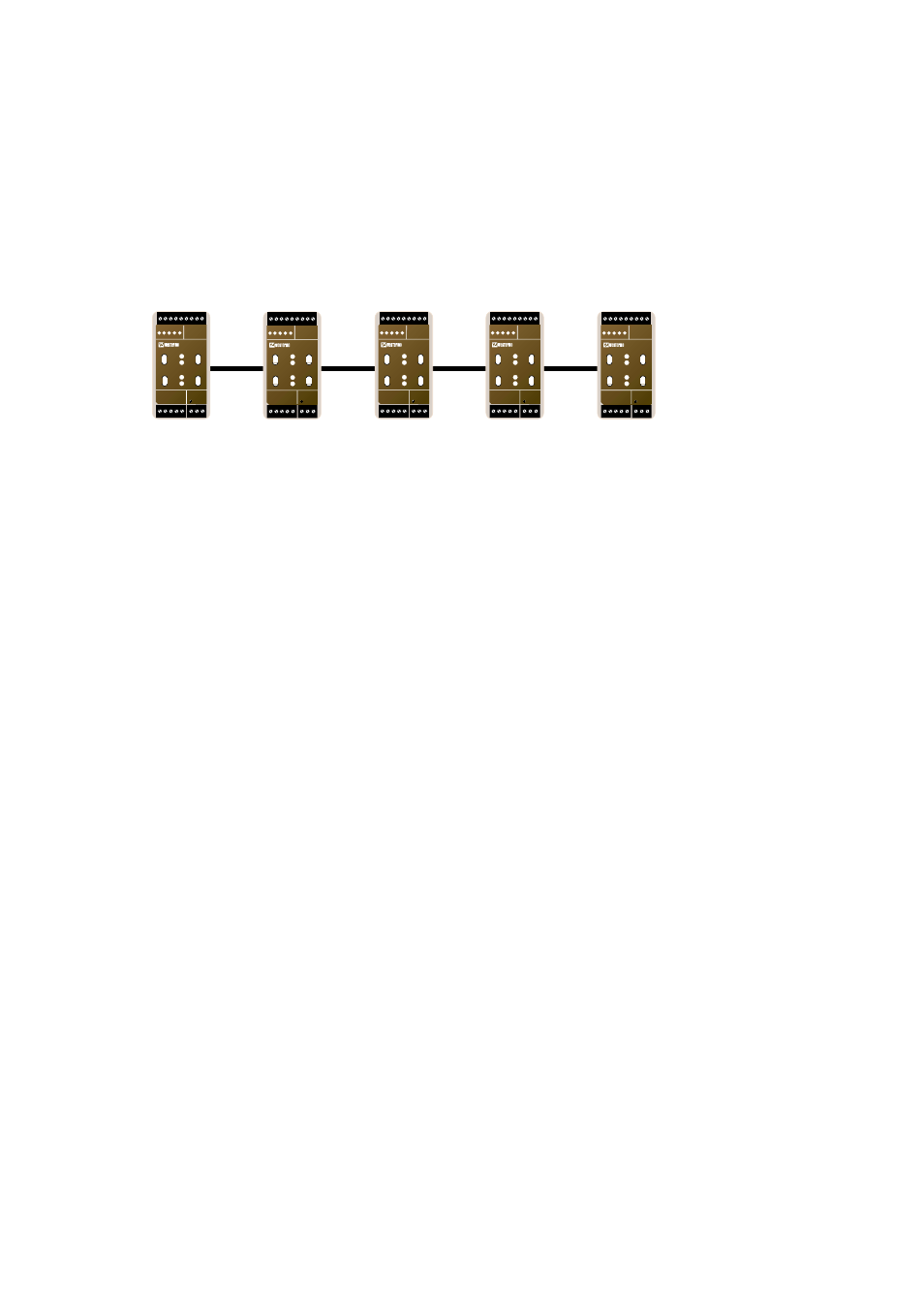
On the fibre channel the devices are attached in a daisy-chain fashion. The signal path is
through each device, that is the packet passes through each device on its way. The signal
is regenerated each time it passes through a device, thus very long distances network
could be built.
The time of propagation depends on the distance and the number of devices to
pass through. The propagation delay affects the channel communication parameters.
By default the LR-11 has been programmed with communication parameters suitable
for a relative small to medium fibre network that follows the below equation:
Fibre distance (m) / 200 + N < 72
For example the above equation would allow 4 LR-11 units to use maximum fibre optic
cable length of 13.6 km.
For larger networks the LR-11 can be programmed with communication parameters
compensating for longer propagation delays. With parameters for large network the
following equation can be used.
Fibre distance (m) / 200 + N < 576
For example, the above equation would allow 8 LR-11 units to use maximum fibre optic
cable length of 113.6 km. Observe however that the maximum allowed fibre length
between two LR-11 units is 25 km (using single mode) depending on the performance of
the fibre optic transmitter and receiver.
See section 4.2 for power budget tables.
See application note AN-01201B for more details about channel performance and chang-
ing the communication parameters.
Fibre Optic channel
TP/FT
Channel 1
TP/FT
Channel 2
TP/FT
Channel 3
TP/FT
Channel 4
TP/FT
Channel 5
N1 N2
L
N
LR-11
LONWORKS TP/FT-10
POWER
Rx1
Rx2
Tx1
Tx2
TD RD ASRV BSRV
C
E
PWR
OPTO LINK MONITOR
CH1
C
E
CH2
N1 N2
L
N
LR-11
LONWORKS TP/FT-10
POWER
Rx1
Rx2
Tx1
Tx2
TD RD ASRV BSRV
C
E
PWR
OPTO LINK MONITOR
CH1
C
E
CH2
N1 N2
L
N
LR-11
LONWORKS TP/FT-10
POWER
Rx1
Rx2
Tx1
Tx2
TD RD ASRV BSRV
C
E
PWR
OPTO LINK MONITOR
CH1
C
E
CH2
N1 N2
L
N
LR-11
LONWORKS TP/FT-10
POWER
Rx1
Rx2
Tx1
Tx2
TD RD ASRV BSRV
C
E
PWR
OPTO LINK MONITOR
CH1
C
E
CH2
N1 N2
L
N
LR-11
LONWORKS TP/FT-10
POWER
Rx1
Rx2
Tx1
Tx2
TD RD ASRV BSRV
C
E
PWR
OPTO LINK MONITOR
CH1
C
E
CH2
Figure 4.1 One fibre channel and multiple TP/FT channels.