Westermo LR-11 User Manual
Page 6
6
6608-2211
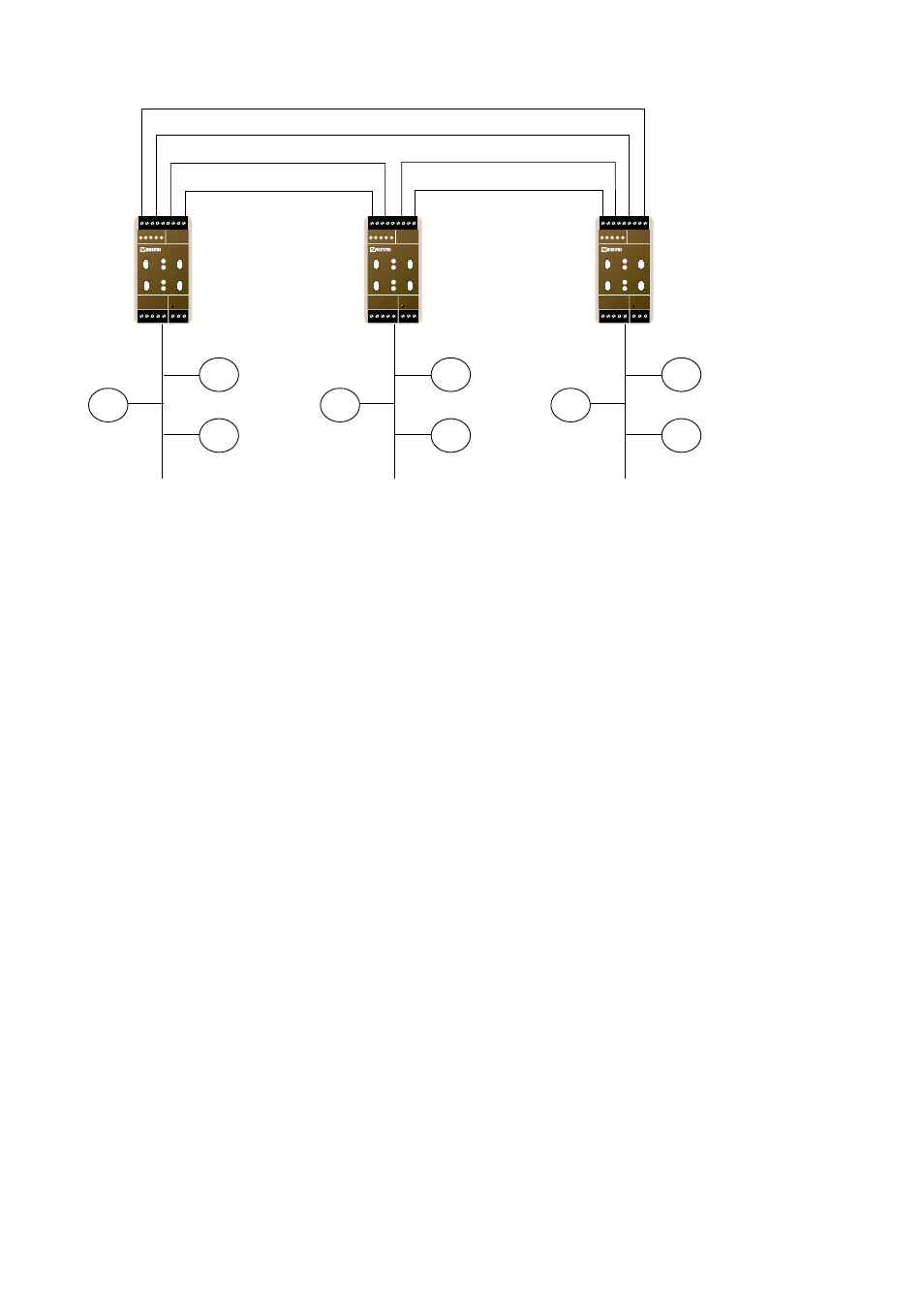
Figure 2.2 Network topologies
Fibre optic channel
LR-11
Ring master
LR-11
LR-11
TP Network
channel 1
TP Network
channel 1
TP Network
channel 1
N1 N2
L
N
LR-11
LONWORKS TP/FT-10
POWER
Rx1
Rx2
Tx1
Tx2
TD RD ASRV BSRV
C
E
PWR
OPTO LINK MONITOR
CH1
C
E
CH2
N1 N2
L
N
LR-11
LONWORKS TP/FT-10
POWER
Rx1
Rx2
Tx1
Tx2
TD RD ASRV BSRV
C
E
PWR
OPTO LINK MONITOR
CH1
C
E
CH2
N1 N2
L
N
LR-11
LONWORKS TP/FT-10
POWER
Rx1
Rx2
Tx1
Tx2
TD RD ASRV BSRV
C
E
PWR
OPTO LINK MONITOR
CH1
C
E
CH2
In a fibre ring, one of the LR-11 units will be assigned as a ring master and then having
the responsibility to stop messages from looping around the ring. The LR-11 has a built-
in redundancy scheme that provides for fault tolerances in the fibre rings. There is a
maximum transmission distance on the fibre link depending on the available power
budget of the LR-11 units and losses due to attenuation in cables, connectors and splice
joints. With single mode fibre, distances up to 25 km can be reached.
For the fibre channel communication parameters, the LR-11 is by default set with param-
eters used for small network. Depending on the fibre length and the number of devices
the communication parameters may be changed to optimize performance. Section 4 will
discuss this matter in further detail.