2 connections, Network connection (l, Tp/ft) (5-position screw terminal) – Westermo LR-11 User Manual
Page 16: Power connection hv (3-position screw terminal), Power connection lv (2-position screw terminal), Alarm connection (9-position screw terminal)
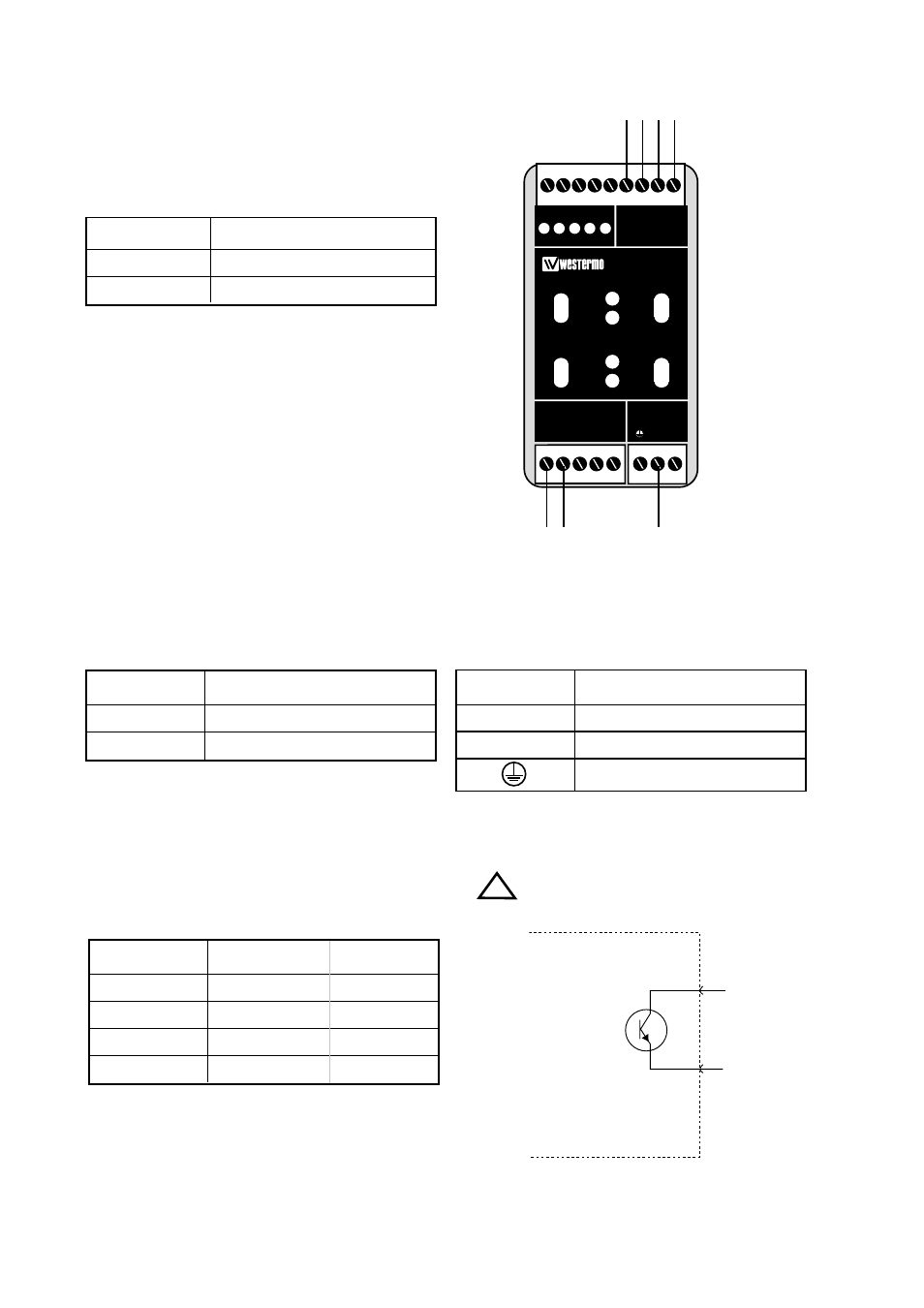
6.2 Connections
Alarm indication
16
6608-2211
Network connection
(L
ON
W
ORKS
®
TP/FT)
(5-position screw terminal)
Connection no.
Description
1
N 1
2
N 2
Power connection HV
(3-position screw terminal)
Connection
Description
L
– high voltage
N
+ high voltage
protective earth
Power connection LV
(2-position screw terminal)
Connection
Description
1
– low voltage
2
+ low voltage
N1 N2
L
N
LR-11
LONWORKS TP/FT-10
POWER
Rx1
Rx2
Tx1
Tx2
TD
RD ASRV ASRV
C
E
PWR
OPTO LINK MONITOR
CH1
C
E
CH2
L
ON
W
ORKS
®
TP/FT
Power
supply
Alarm connectors are polarity depended.
Alarm signals
Upon failure the circuit between the contacts “C” and
“E” is opened. This circuit can be used to generate an
external alarm signal by connecting an external relay as
shown on page 17. Please note that the maximum
allowed voltage/current is 30 V/80 mA.
Alarm connection
(9-position screw terminal)
Connection
Description
Polarity
1
CH2, E
–
2
CH2, C
+
3
CH1, E
–
4
CH1, C
+
Note
!
C
E