A lontalk, Lr-11, Tp network – Westermo LR-11 User Manual
Page 8: Tp network lr-11pp tp network lr-11pp, Rx tx1 rx2 tx1, Rx tx rx tx
8
6608-2211
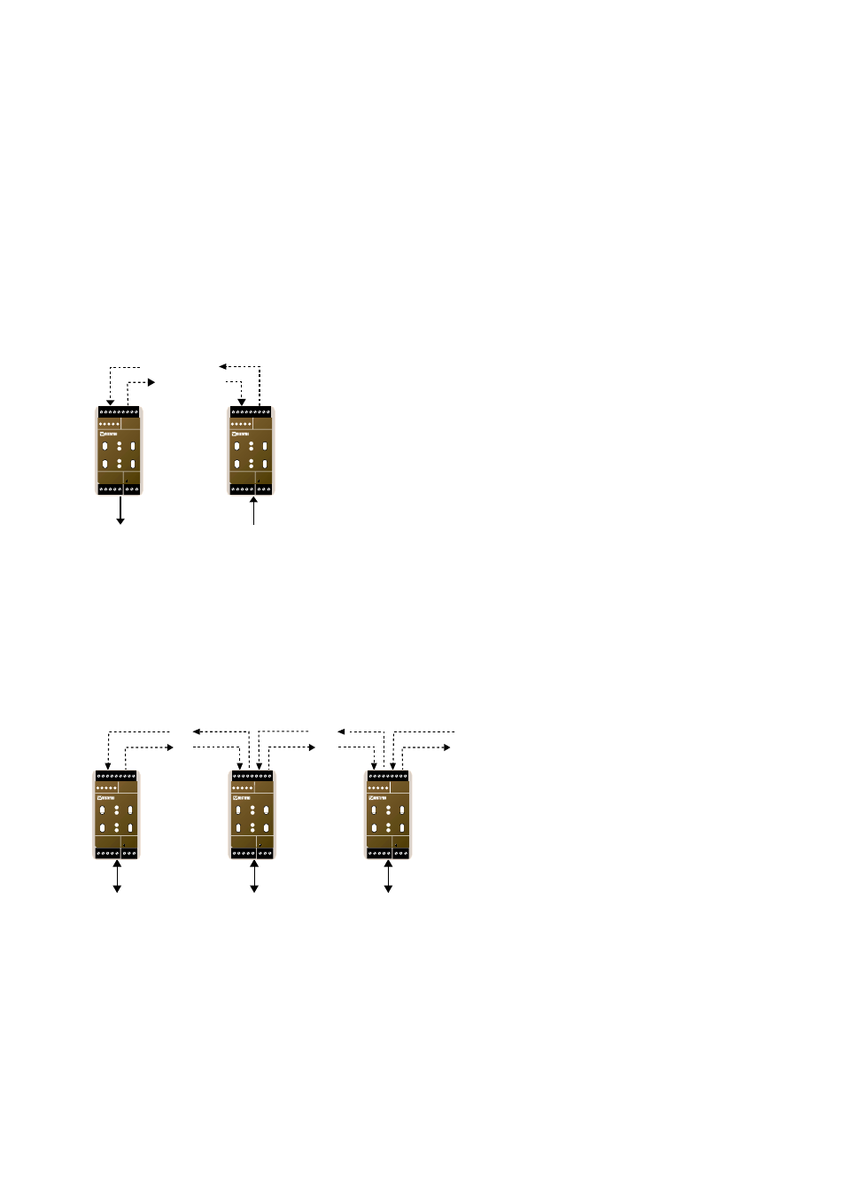
3.2 Bus topology
Using the LR-11 unit gives the possibility to create a fibre optic bus topology.
The data flow is schematically illustrated in figure 3.4.
Figure 3.4 Bus communication
Figure 3.3 Point to point communication
LR-11
LR-11PP
Rx
Tx1
Rx2
Tx1
LR-11
Rx2
Tx1
Rx1
Tx2
Rx1
Tx2
TP Network
TP Network
TP Network
N1 N2
L
N
LR-11
LONWORKS TP/FT-10
POWER
Rx1
Rx2
Tx1
Tx2
TD RD ASRV BSRV
C
E
PWR
OPTO LINK MONITOR
CH1
C
E
CH2
N1 N2
L
N
LR-11
LONWORKS TP/FT-10
POWER
Rx1
Rx2
Tx1
Tx2
TD RD ASRV BSRV
C
E
PWR
OPTO LINK MONITOR
CH1
C
E
CH2
N1 N2
L
N
LR-11
LONWORKS TP/FT-10
POWER
Rx1
Rx2
Tx1
Tx2
TD RD ASRV BSRV
C
E
PWR
OPTO LINK MONITOR
CH1
C
E
CH2
A LonTalk
®
packet received on the fibre channel is always forwarded to the next unit on
the fibre channel. Depending on the packets destination address and router configuration
it may also be forwarded onto the TP/FT channel.
3.1 Point to point topology
With only two network segments, the most cost effective solution is to use two point to
point (LR-11PP) units to create a fibre optic connection.
The user could however still choose not to use the point to point units and have the
additional link unconnected. In this way the user have the possibility to easily add more
units and network segments at a later time.
Figure 3.3 schematically illustrates the data flow in the point to point communication
mode.
TP Network
LR-11PP
TP Network
LR-11PP
Rx
Tx
Rx
Tx
N1 N2
L
N
LR-11
LONWORKS TP/FT-10
POWER
Rx1
Rx2
Tx1
Tx2
TD RD ASRV BSRV
C
E
PWR
OPTO LINK MONITOR
CH1
C
E
CH2
N1 N2
L
N
LR-11
LONWORKS TP/FT-10
POWER
Rx1
Rx2
Tx1
Tx2
TD RD ASRV BSRV
C
E
PWR
OPTO LINK MONITOR
CH1
C
E
CH2