Single or multimode lc fibre connectors, Status interface – Westermo LRW-102 User Manual
Page 12
12
6650-2260
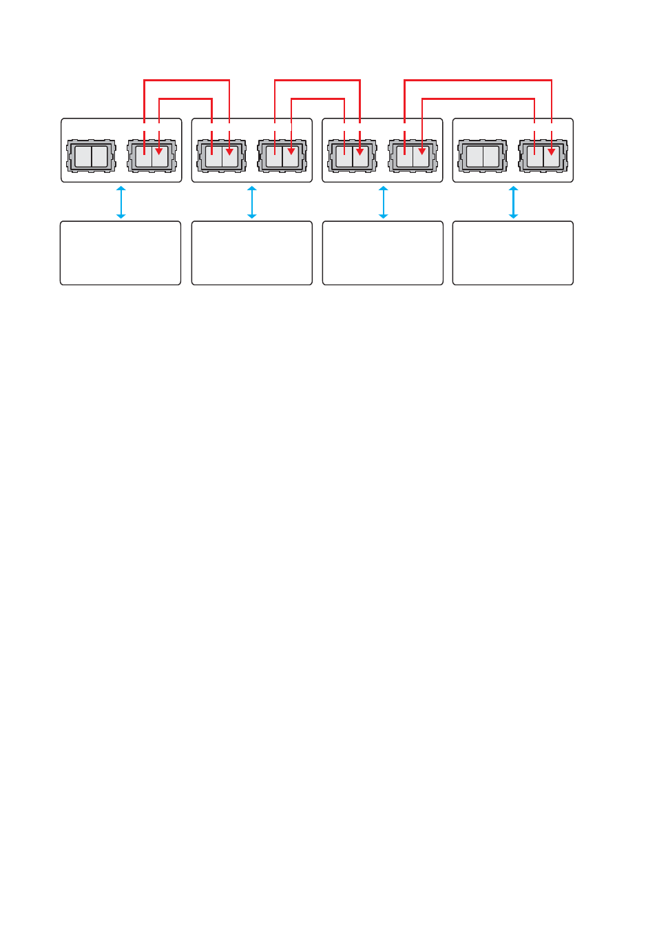
Bus or multidrop communications via fibre optic network
TX
RX
TX
RX
TX
RX
TX
RX
TX
RX
TX
RX
TX
RX
TX
RX
CH 2
CH 1
CH 2
CH 1
CH 2
CH 1
CH 2
CH 1
LON
Network
LON
Network
LON
Network
LON
Network
The data is transferred via the fibre optic network to the serial ports of all units. If
LRW-102 is connected to two optical fibre links (mid unit) converted data will be trans-
mitted in both directions, via both CH 1 and CH 2. With only one optical fibre link (end
unit) converted data will be transmitted in one direction, via CH 1 only. Data received
from one LRW-102 optical fibre port will be repeated through the other optical fibre
port and it will also convert the frame to serial data.
Optical fibre link functionality and status indication
At power on, all LED's will be active during an initiation sequence followed by an auto-
matic initiation of the optical fibre links. The alarm will be set until the fibre optical links
are in operation and ready to transfer serial data.
Data can be transferred over a fibre optical link as long as the link is in operation, indi-
cated by active CH1 respective CH2.
When any of the fibre optical links is out of operation and this is a faulty state, will it be indi-
cated by a local alarm and set the alarm output. It will also send a remote alarm via the other
link, if possible. When the link returns to operations mode, the alarm will reset automatically.
Redundant power supply, galvanic isolated (2 kVAC) to other ports.
LRW-102 (LRW-102PP) should be supplied with safety extra low voltage (SELV). It is
designed to operate permanently over a wide input range and provided with two inde-
pendent inputs, allowing redundancy should either supply fail.
Single or multimode LC fibre connectors
The LRW-102 (LRW-102PP) uses Small Form Factor Pluggable (SFP) transceivers that
are in compliance with Multi-Sourcing Agreement (MSA). A wide range of different fibre
transceivers and connectors can be used.
Note: Bi-Di fibre can be used.
Status interface
This interface enables supervision of fibre optic link state.<8 ohm means that status is OK.
The fault state will be set if:
Local or remote fibre link errors exist.
…
… The unit is out of service, e.g. no power supply.