Displaying and maintaining isolate-user-vlan, Isolate-user-vlan configuration example, Network requirements – H3C Technologies H3C S10500 Series Switches User Manual
Page 158
147
NOTE:
•
After you complete the preceding configurations, make sure that the isolate-user-VLAN is the PVID of the
upstream port and the secondary VLAN is the PVID of the downstream port. For hybrid ports that have
been assigned to the isolate-user-VLAN and secondary VLANs in tagged mode, H3C recommends that
you assign these ports to these VLANs in untagged mode.
•
An isolate-user-VLAN will automatically synchronize the MAC address entries of the associated
secondary VLANs.
•
You cannot configure the member port of a service loopback group as the uplink or downlink port of an
isolate-user-VLAN. For more information about the service loopback group, see the chapter “Service
loopback group configuration.”
Displaying and maintaining isolate-user-VLAN
To do...
Use the command...
Remarks
Display the mapping between an
isolate-user-VLAN and its secondary
VLANs
display isolate-user-vlan
[ isolate-user-vlan-id ] [ | { begin |
exclude | include } regular-expression ]
Available in any view
Isolate-user-VLAN configuration example
Network requirements
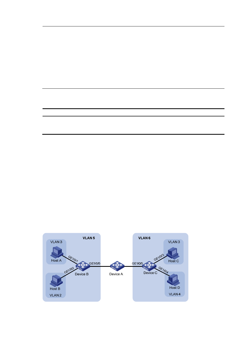
As shown in
•
Connect Device A to downstream devices Device B and Device C.
•
Configure VLAN 5 on Device B as an isolate-user-VLAN, assign the uplink port GigabitEthernet
1/0/5 to VLAN 5, and associate VLAN 5 with secondary VLANs VLAN 2 and VLAN 3. Assign
GigabitEthernet 1/0/2 to VLAN 2 and GigabitEthernet 1/0/1 to VLAN 3.
•
Configure VLAN 6 on Device C as an isolate-user-VLAN, assign the uplink port GigabitEthernet
1/0/5 to VLAN 6, and associate VLAN 6 with secondary VLANs VLAN 3 and VLAN 4. Assign
GigabitEthernet 1/0/3 to VLAN 3 and GigabitEthernet 1/0/4 to VLAN 4.
•
As far as Device A is concerned, Device B only has VLAN 5 and Device C only has VLAN 6.
Figure 46 Network diagram