Qinq frame structure – H3C Technologies H3C S10500 Series Switches User Manual
Page 184
173
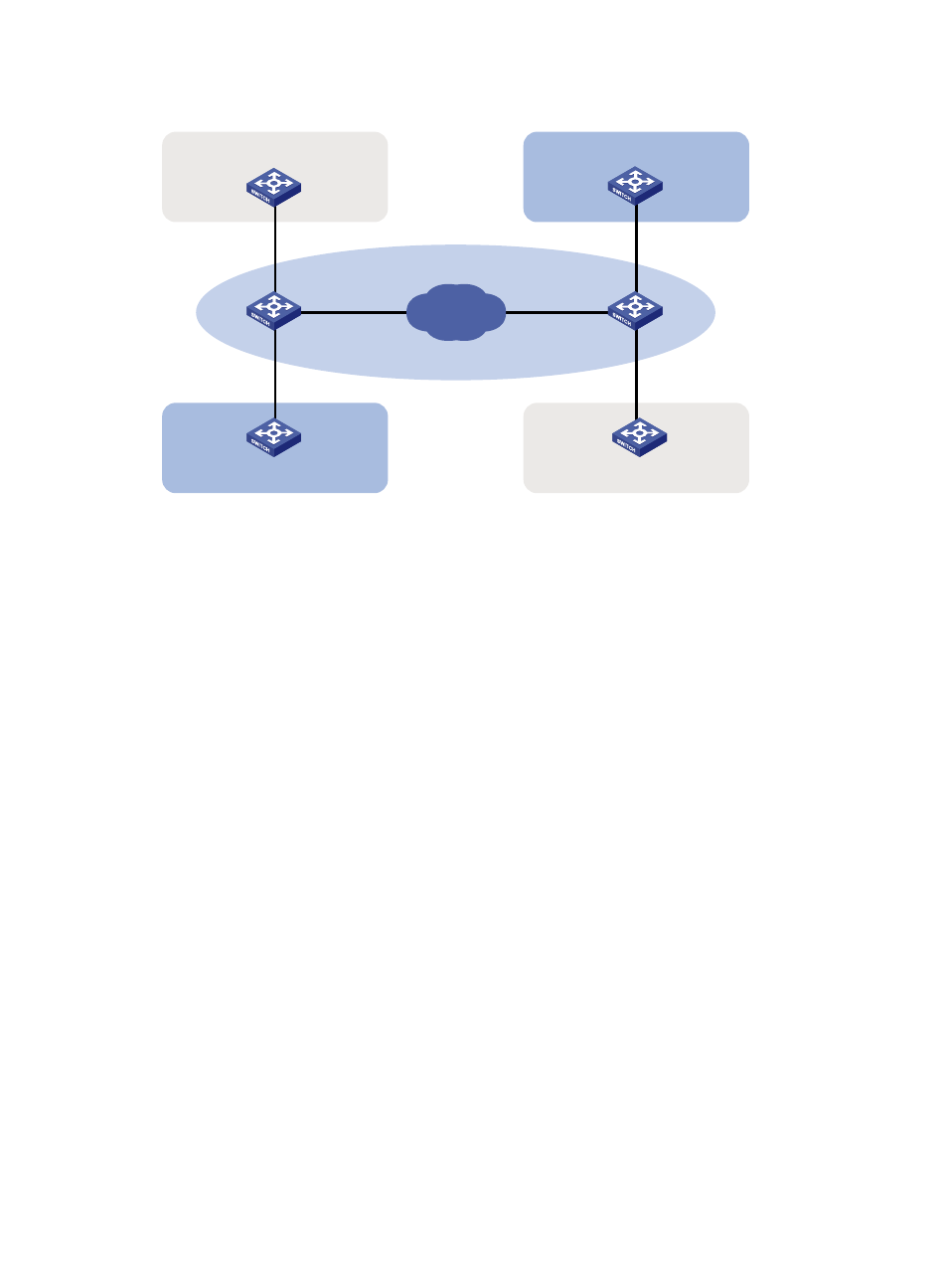
Figure 56 Typical QinQ application scenario
CE 1
Customer
network A
PE 1
Public network
PE 2
CE 2
VLANs 1 to 10
VLANs 1 to 20
CE 3
VLANs 1 to 20
VLANs 1 to 10
CE 4
Customer
network A
Customer
network B
Customer
network B
IP network
VLAN 4
VLAN 4
VLAN 3
VLAN 3
As shown in
, customer network A has CVLANs 1 through 10, and customer network B has
CVLANs 1 through 20. The service provider assigns SVLAN 3 for customer network A, and assigns
SVLAN 4 for customer network B.
When a tagged Ethernet frame from customer network A arrives at a provider edge device (PE), the PE
tags the frame with outer VLAN 3. When a tagged Ethernet frame from customer network B arrives at a
PE, the PE tags the frame with outer VLAN 4. There is no overlap of VLAN IDs among customers, and
traffic from different customers can be identified separately.
The double-tagged Ethernet frame is then transmitted over the service provider network and arrives at the
other PE. The PE removes the SVLAN of the frame before sending it to the target customer edge device
(CE).
QinQ frame structure
A QinQ frame is transmitted double-tagged over the service provider network. As shown in
inner VLAN tag is the CVLAN tag, and the outer one is the SVLAN tag that the service provider has
allocated to the customer.
QinQ uses CVLAN tags to transmit frames over the private network, and uses SVLAN tags to transmit
frames over the public network. When a QinQ frame is transmitted over the public network, its CVLAN
tag is transmitted as the payload.