100/1000base-x sfp port, Figure 78, N in – H3C Technologies H3C S5560 Series Switches User Manual
Page 93: Figure 79, Figure 80
Advertising
84
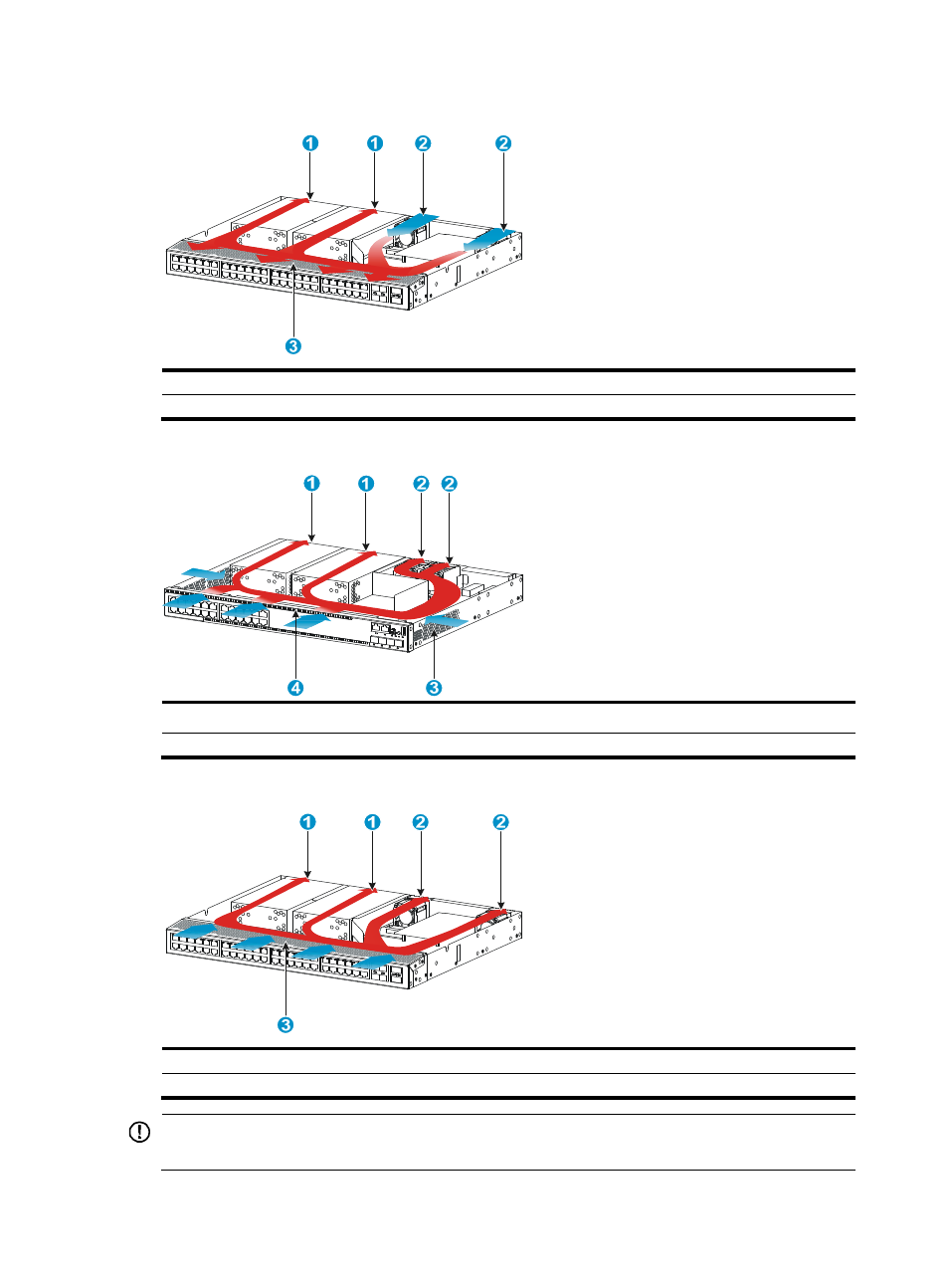
Figure 78 Airflow through the S5560-54QS-EI switch with the LSPM1FANSA fan tray
(1) Power module air vents
(2) Fan tray air vents
(3) Port side air vents
Figure 79 Airflow through the S5560-30C-EI switch with the LSPM1FANSB fan tray
(1) Power module air vents
(2) Fan tray air vents
(3) Air vents in the switch side
(4) Port side air vents
Figure 80 Airflow through the S5560-54QS-EI switch with the LSPM1FANSB fan tray
(1) Power module air vents
(2) Fan tray air vents
(3) Port side air vents
IMPORTANT:
The chassis and the power modules use separate air aisles. Make sure both aisles are not blocked.
Advertising
This manual is related to the following products: