S5500-28c-pwr-ei – H3C Technologies H3C S5500 Series Switches User Manual
Page 15
7
CAUTION:
•
The S5500-28F-EI is shipped with the two expansion interface card slots covered by filler panels. You
can select one or two interface cards for your switch as needed. For the interface cards available for the
S5500-EI Switch Series, see "
." For how to install an interface card, see "
•
The S5500-28F-EI switch is shipped with power module slot 1 installed with a power module and power
module slot 2 installed with a filler panel. You can install a power module in PWR2 to serve as a backup.
For more information about the available power modules, see "
"
For
how to install and remove a power module, see "
Installing and removing a hot swappable power
."
S5500-28C-PWR-EI
The S5500-28C-PWR-EI includes two models: PoE and PoE+.
•
The front panels of the PoE and PoE+ models are the same in appearance. See
.
•
The PoE+ model has a PoE+ label on its rear panel, as shown in
. The maximum PoE power
per port is 30 W.
•
The PoE model has no PoE+ label on its rear panel, as shown in
. The maximum PoE power
per port is 15.4 W.
For more information about the PoE power supply, see
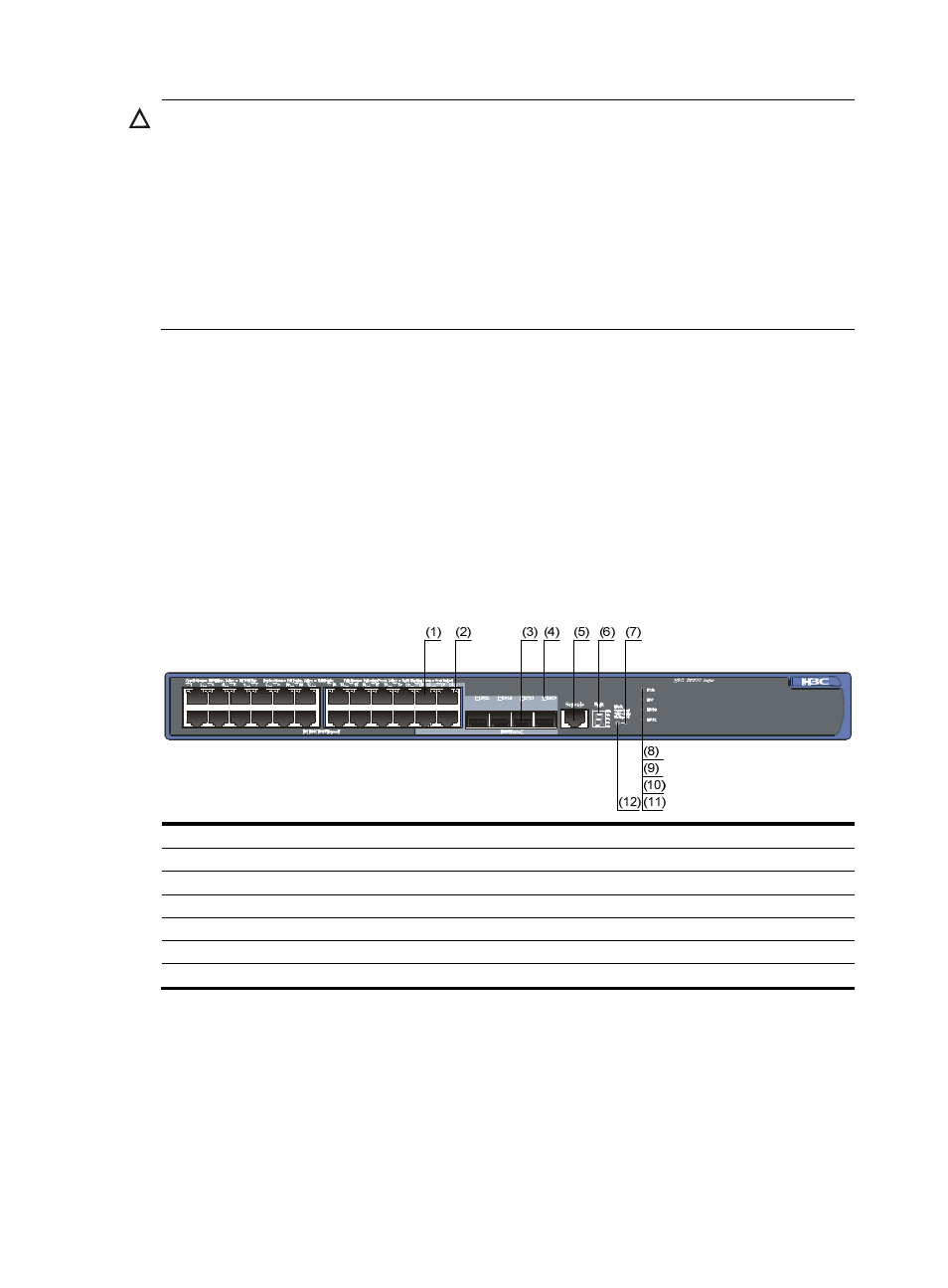
Figure 8 Front panel of the S5500-28C-PWR-EI switch
(1) 10/100/1000 Base-T auto-sensing Ethernet port
(2) 10/100/1000 Base-T auto-sensing Ethernet port status LED
(3) 1000 Base-X SFP port
(4) 1000Base-X SFP port status LED
(5) Console port
(6) Seven-segment LED
(7) Port mode LED (Mode)
(8) System status LED (PWR)
(9) RPS status LED (RPS)
(10) Interface card 1 status LED (MOD1)
(11) Interface card 2 status LED (MOD2)
(12) Port status LED mode switching button