Introduction to mounting bracket – H3C Technologies H3C S5500 Series Switches User Manual
Page 34
26
Introduction to mounting bracket
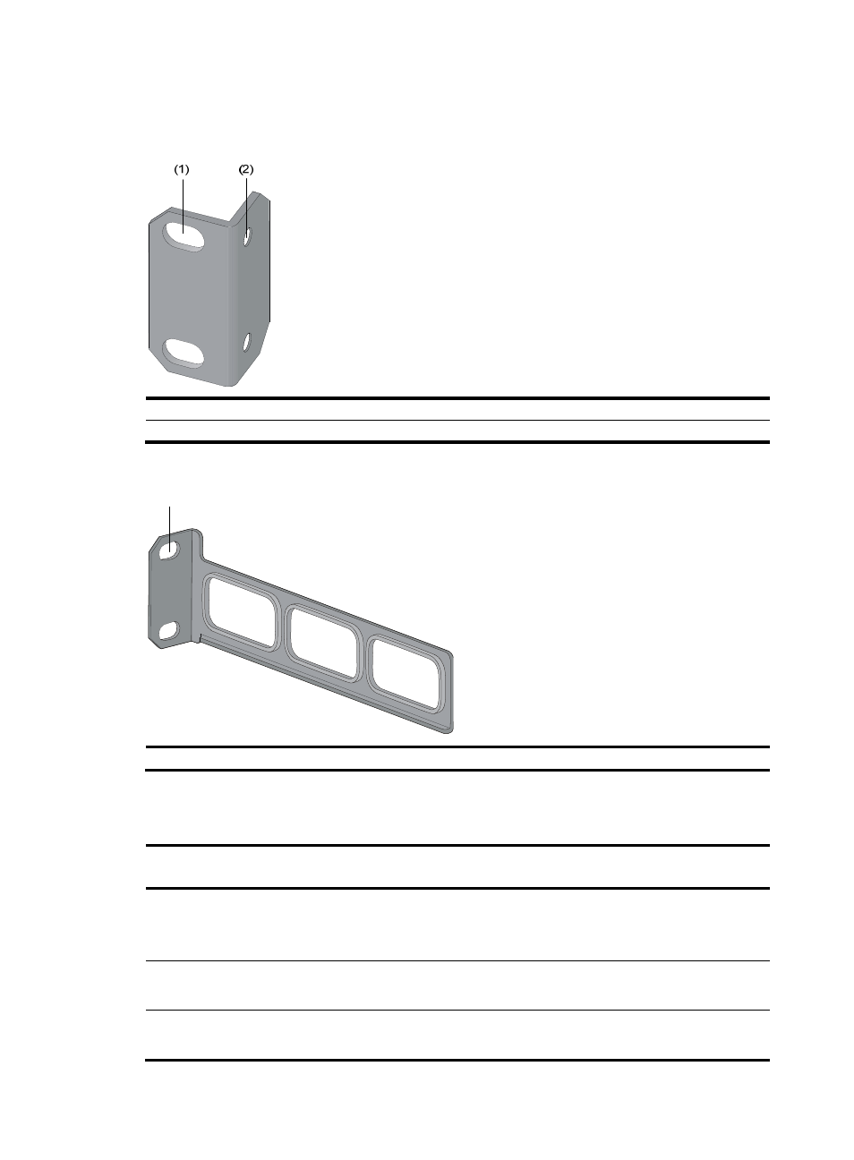
Figure 17 Appearance of a standard front mounting bracket
(1) Screw hole for attaching the mounting bracket to the cabinet (Use one M6 screw)
(2) Screw hole for attaching the switch to the mounting bracket
Figure 18 Appearance of a rear mounting bracket
(1) Screw hole for attaching the mounting bracket to the cabinet (Use one M6 screw)
For the selection of front and rear mounting brackets, see
.
Table 26 Selection of mounting bracket for the S5500-EI Switch Series
Model
Dimensions (H × W × D)
Configuration type of
front mounting bracket
Configuration type of
rear mounting bracket
S5500-28C-EI
S5500-52C-EI
S5500-28C-EI-DC
43.6 × 440 × 300 mm
(1.72 × 17.32 × 11.81 in) Standard N/A
S5500-28C-PWR-EI
S5500-52C-PWR-EI
43.6 × 440 × 420 mm
(1.72 × 17.32 × 16.54 in) Standard Standard
S5500-28F-EI
43.6 × 440 × 360 mm
(1.72 × 17.32 × 14.17 in)
Standard Standard
(1)