Figure 11, Figure 12, N in – H3C Technologies H3C S5500 Series Switches User Manual
Page 17: Figure 13
9
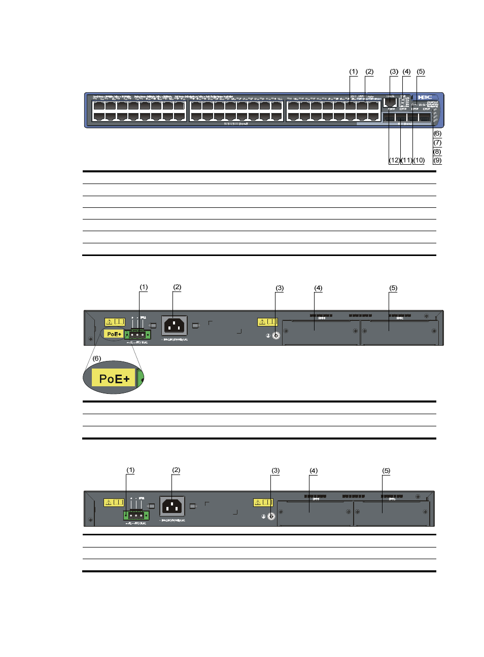
Figure 11 Front panel of the S5500-52C-PWR-EI switch
(1) 10/100/1000 Base-T auto-sensing Ethernet port
(2) 10/100/1000 Base-T auto-sensing Ethernet port status LED
(3) Console port
(4) Seven-segment LED
(5) Port mode LED (Mode)
(6) System status LED (PWR)
(7) RPS status LED (RPS)
(8) Interface card 1 status LED (MOD1)
(9) Interface card 2 status LED (MOD2)
(10) Port status LED mode switching button
(11) 1000 Base-X SFP port
(12) 1000Base-X SFP port status LED
Figure 12 Rear panel of the S5500-52C-PWR-EI switch (PoE+ model)
(1) RPS power input
(2) AC power input
(3) Grounding screw
(4) Interface card slot 1 (MOD1)
(5) Interface card slot 2 (MOD2)
(6) PoE+ label
Figure 13 Rear panel of the S5500-52C-PWR-EI switch (PoE model)
(1) RPS power input
(2) AC power input
(3) Grounding screw
(4) Interface card slot 1 (MOD1)
(5) Interface card slot 2 (MOD2)