Configuration procedure – H3C Technologies H3C S3100V2 Series Switches User Manual
Page 45
37
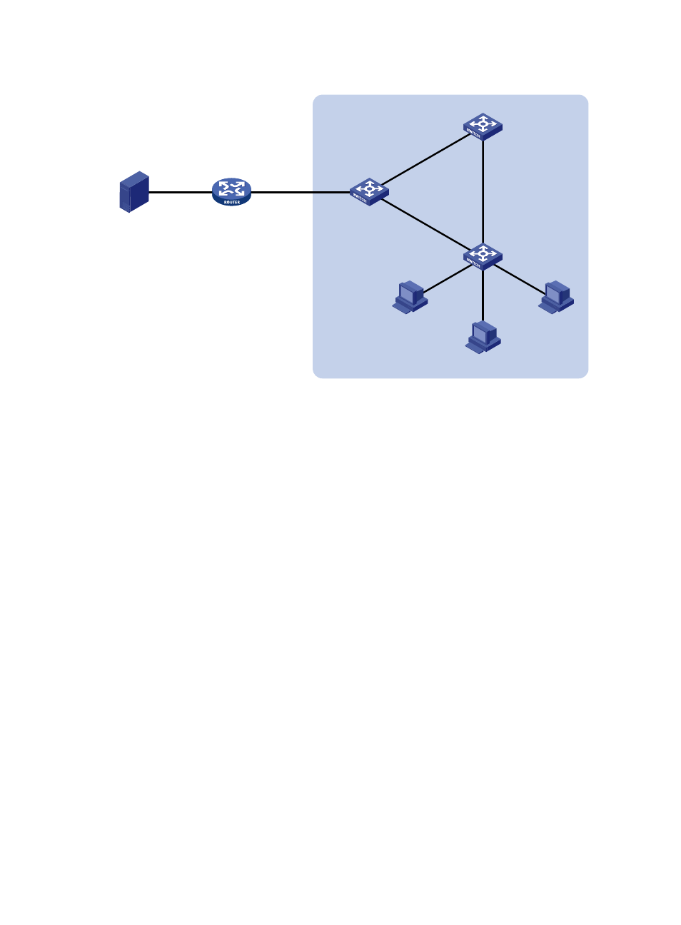
Figure 14 Network diagram for static port configuration
Source
1.1.1.1/24
Router A
IGMP querier
Eth1/0/1
10.1.1.1/24
Switch A
Switch B
Switch C
Eth1/0/1
Et
h1
/0/
2
Eth
1/0
/3
Et
h1
/0/
1
Eth1/0/2
Eth
1/0
/1
Eth
1/0/2
Eth
1/0
/3
Eth1
/0/4
Et
h1
/0/
5
Host A
Receiver
Host B
Host C
Receiver
VLAN 100
Eth1/0/2
1.1.1.2/24
Configuration procedure
1.
Configure IP addresses
Configure an IP address and subnet mask for each interface according to
. The detailed
configuration steps are omitted.
2.
Configure Router A
# Enable IP multicast routing, enable PIM-DM on each interface, and enable IGMP on Ethernet 1/0/1.
<RouterA> system-view
[RouterA] multicast routing-enable
[RouterA] interface ethernet 1/0/0/1
[RouterA-Ethernet1/0/1] igmp enable
[RouterA-Ethernet1/0/1] pim dm
[RouterA-Ethernet1/0/1] quit
[RouterA] interface ethernet 1/0/0/2
[RouterA-Ethernet1/0/2] pim dm
[RouterA-Ethernet1/0/2] quit
3.
Configure Switch A
# Enable IGMP snooping globally.
<SwitchA> system-view
[SwitchA] igmp-snooping
[SwitchA-igmp-snooping] quit
# Create VLAN 100, assign Ethernet 1/0/1 through Ethernet 1/0/3 to this VLAN, and enable IGMP
snooping in the VLAN.
[SwitchA] vlan 100
[SwitchA-vlan100] port ethernet 1/0/1 to ethernet 1/0/3
[SwitchA-vlan100] igmp-snooping enable
[SwitchA-vlan100] quit