Active/standby mode, Load balancing mode, How interface backup works – H3C Technologies H3C MSR 50 User Manual
Page 21
13
How interface backup works
Interface backup operates in active/standby mode or in load balancing mode.
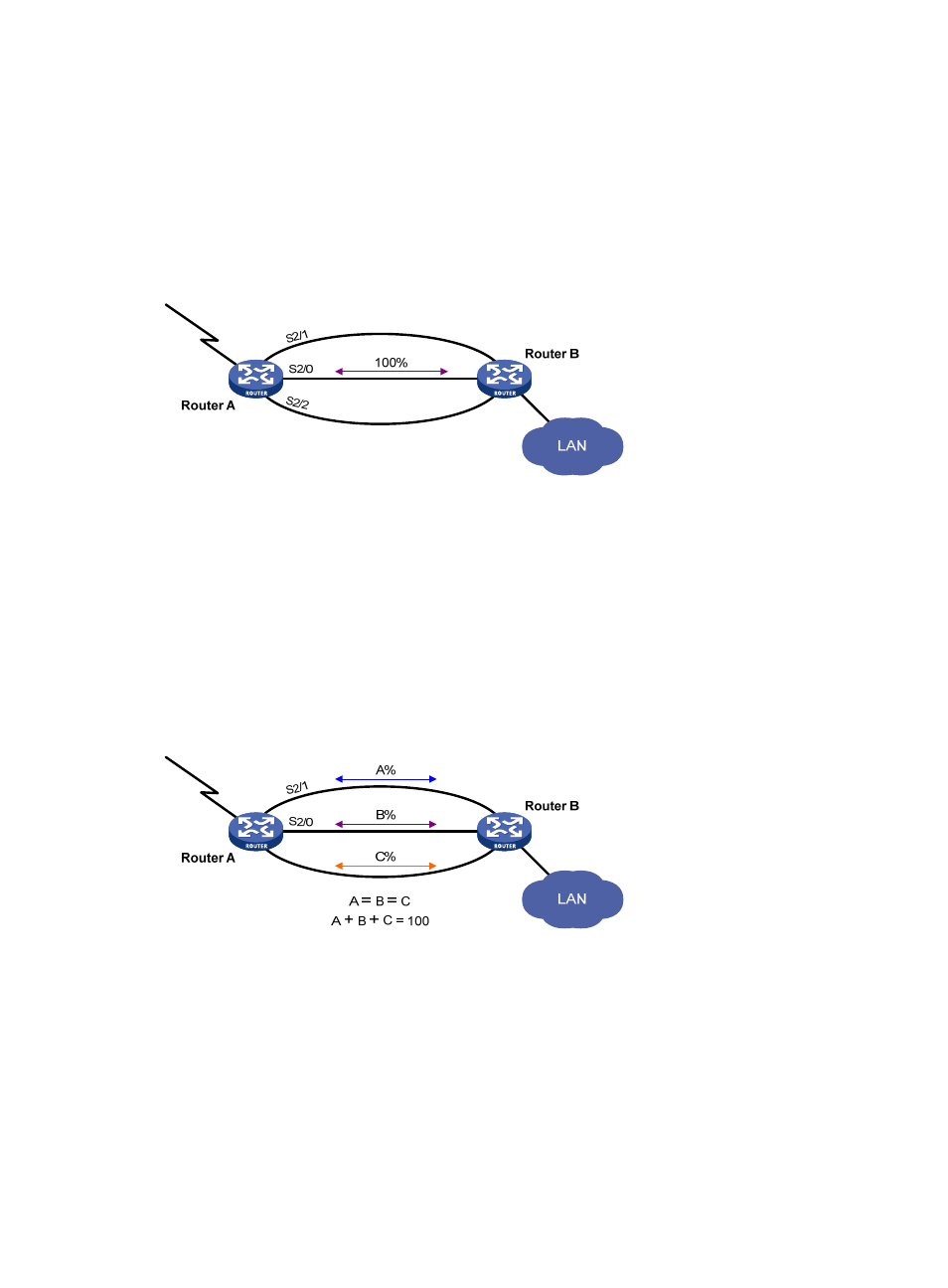
Active/standby mode
As shown in
, interface Serial 2/0 on Router A acts as the active interface and interfaces Serial
2/1 and Serial 2/2 act as the standby interfaces.
Figure 5 Diagram for active/standby mode
In active/standby mode, only one interface transmits data at any given time.
•
When the active interface is operating correctly, even if the traffic is overloaded, the standby
interface is in a backup state. All traffic is transmitted by the active interface.
•
If the active interface fails, the standby interface with highest priority takes over to transmit data.
•
When the active interface is restored, it resumes data transmission.
Load balancing mode
As shown in
, interface Serial 2/0 on Router A acts as the active interface, and interfaces Serial
2/1 and Serial 2/2 act as the standby interfaces.
Figure 6 Diagram for load balancing mode
In load balancing mode, you can set an upper threshold (enable-threshold) and a lower threshold
(disable-threshold). Traffic can be shared among multiple interfaces:
•
When the traffic on the active interface exceeds the predefined enable-threshold, the highest
priority standby interface is activated. Other standby interfaces are activated in descending priority
order if exceeding traffic still exists.
•
When the traffic on the active interface decreases below the predefined disable-threshold, the
system shuts down the lowest priority standby interface first and then shuts down the other standby
interfaces in ascending priority order depending on traffic size.
S2/2