Network requirements, Configuration procedure – H3C Technologies H3C WX3000E Series Wireless Switches User Manual
Page 59
51
VRRP-track-interface management collaboration configuration
example (the master monitors the uplink interface)
Network requirements
•
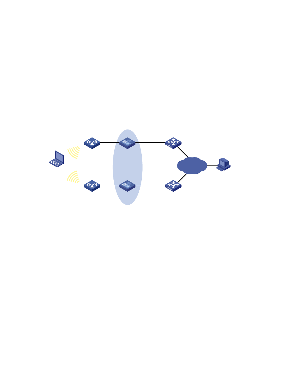
As shown in
, Client needs to access Host on the Internet. The default gateway of Client
is 10.1.1.10/24.
•
AC 1 and AC 2 belong to VRRP group 1, whose virtual IP address is 10.1.1.10.
•
When AC 1 works properly, packets from Client to Host are forwarded through AC 1. When VRRP
detects that there is a fault on the uplink interface of AC 1 through the interface management
module, packets from Client to Host are forwarded through AC 2.
Figure 20 Network diagram
Configuration procedure
1.
Create VLANs, and assign corresponding ports to the VLANs, and configure the IP address of
each VLAN interface as shown in
2.
Configure a track entry on AC 1:
# Configure track entry 1, and associate it with the physical status of the uplink interface
VLAN-interface 3.
[AC1] track 1 interface vlan-interface 3
3.
Configure VRRP on AC 1:
# Create VRRP group 1, and configure the virtual IP address 10.1.1.10 for the group.
[AC1] interface vlan-interface 2
[AC1-Vlan-interface2] vrrp vrid 1 virtual-ip 10.1.1.10
# Set the priority of AC 1 in VRRP group 1 to 110.
[AC1-Vlan-interface2] vrrp vrid 1 priority 110
# Configure to monitor track entry 1 and specify the priority decrement as 30.
[AC1-Vlan-interface2] vrrp vrid 1 track 1 reduced 30
4.
Configure VRRP on AC 2:
<AC2> system-view
[AC2] interface vlan-interface 2
# Create VRRP group 1, and configure the virtual IP address 10.1.1.10 for the group.
AC 1
AC 2
Virtual IP address:
10.1.1.10/24
Vlan-int2
10.1.1.1/24
Vlan-int2
10.1.1.2/24
Host
Client
10.1.1.3/24
20.1.1.1/24
Internet
Vlan-int3
10.1.2.1/24
Vlan-int3
10.1.3.1/24
Vlan-int3
10.1.3.2/24
Vlan-int3
10.1.2.2/24
Switch A
Switch B
AP 1
AP 2
- H3C WX5500E Series Access Controllers H3C WX3500E Series Access Controllers H3C WX2500E Series Access Controllers H3C WX6000 Series Access Controllers H3C WX5000 Series Access Controllers H3C LSWM1WCM10 Access Controller Module H3C LSUM3WCMD0 Access Controller Module H3C LSUM1WCME0 Access Controller Module H3C LSWM1WCM20 Access Controller Module H3C LSQM1WCMB0 Access Controller Module H3C LSRM1WCM2A1 Access Controller Module H3C LSBM1WCM2A0 Access Controller Module