Single vrrp group configuration example, Network requirements, Configuration procedure – H3C Technologies H3C SecPath F1000-E User Manual
Page 38
37
•
VRRP Interface Tracking Configuration Example
•
Multiple VRRP Group Configuration Example
•
VRRP Load Balancing Mode Configuration Example
Single VRRP Group Configuration Example
Network requirements
•
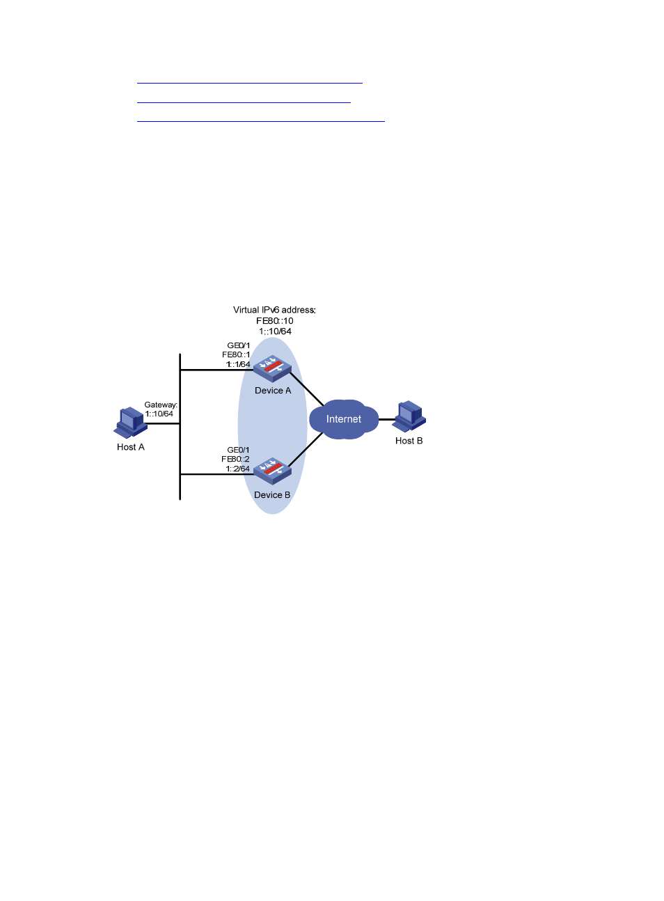
Host A needs to access Host B on the Internet, using 1::10/64 as its default gateway.
•
Device A and Device B belong to VRRP group 1 with the virtual IPv6 addresses of 1::10/64 and
FE80::10.
•
If Device A operates normally, packets sent from Host A to Host B are forwarded by Device A; if
Device A fails, packets sent from Host A to Host B are forwarded by Device B.
Figure 14 Network diagram for single VRRP group configuration
Configuration procedure
Step1
Configure Device A
<DeviceA> system-view
[DeviceA] ipv6
[DeviceA] interface gigabitethernet 0/1
[DeviceA-GigabitEthernet0/1] ipv6 address fe80::1 link-local
[DeviceA-GigabitEthernet0/1] ipv6 address 1::1 64
# Create a VRRP group 1 and set its virtual IPv6 addresses to FE80::10 and 1::10.
[DeviceA-GigabitEthernet0/1] vrrp ipv6 vrid 1 virtual-ip fe80::10 link-local
[DeviceA-GigabitEthernet0/1] vrrp ipv6 vrid 1 virtual-ip 1::10
# Configure the priority of Device A in VRRP group 1 as 110.
[DeviceA-GigabitEthernet0/1] vrrp ipv6 vrid 1 priority 110
# Set Device A to work in preemptive mode, with the preemption delay set to 5 seconds.
[DeviceA-GigabitEthernet0/1] vrrp ipv6 vrid 1 preempt-mode timer delay 5
# Enable Device A to send RA messages.
[DeviceA-GigabitEthernet0/1] undo ipv6 nd ra halt