1 connecting the studio intercom system – Grass Valley HD Wireless User Manual
Page 28
28
HD Wireless User’s Guide (v6.2)
Chapter 2 - Installation
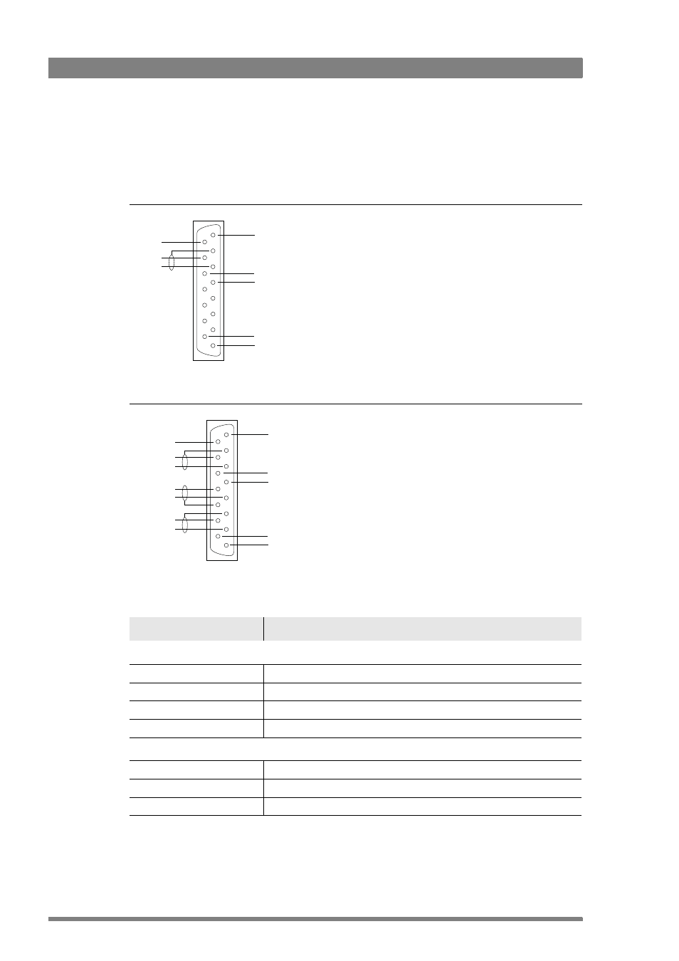
2.4.1 Connecting the studio intercom system
Connect the studio intercom system to the I/Com connector on the rear of the WCU. The
wiring of the panel connector is shown below for two-wire and four-wire systems.
Figure 2-8. Intercom connection - two-wire system
Figure 2-9. Intercom connection - four-wire system
Table 2-10. Intercom signal specifications
Function
Value
4-wire
Output signal level
+6 dBu nominal into 10 K
(adjustable range: +12 dBu)
Output impedance
600
(max), symmetrical
Input signal reference level
+6 dBu or 0 dBu selectable
Input impedance
9 K
(min), symmetrical
2-wire
Signal level
0 dBu
Load impedance
> 200
DC level
10 VDC maximum
1
9
15
8
Housing
Housing
PROG
ENG in/out
-
+
-
+
PROD in/out
-
+
1
9
15
8
Housing
Housing
ENG out
-
+
PROD in
PROD in ret
.
ENG in
ENG in ret
.
PROG in
PROG in ret
.
PROD out
-
+