Serial protocol – Grass Valley VM 3000 System Controllers v.7.4 User Manual
Page 235
Configurator
Serial Protocol Table
5−25
VM 3000 Installation and Operating Manual
Serial Protocol
The Serial Protocol table must be used when a VM/SI controller board is first connected to VTRs, control panels, and other
serial control devices. This includes “remote” (third party) switchers.
†
This table is also used when a Saturn video processor serves as a connection point for an MPK bus, when a PC acts as a Soft-
ware Control Panel.
‡
It is also used to configure the serial ports of the CM 4000 Control Module.
§
2
3
Serial Protocol
1
SNY
SI1
SI2
MPK
VM1
MPK
Board
(CM 1)
Protocol 1/2 -
SNY
MPK
MPK
(CM 2)
Protocol 3/4 -
MPK
MPK
MPK
(CM 3)
Protocol 5/6 -
AMP
MPK
TCS
(CM 4)
Protocol 7/8 -
ES
MPK
UND
(CM 5)
Protocol 9/10 -
UND
UND
UND
11/12 - (CM 6)
Protocol
UND
UND
UND
13/14 - (CM 7)
Protocol
UND
UND
UND
15/16 - (CM 8)
Protocol
38400
(CM 1)
Baud 1/2 -
(CM 2)
Baud 3/4 -
(CM 3)
Baud 5/6 -
(CM 4)
Baud 7/8 -
(CM 5)
Baud 9/10 -
(CM 6
Baud 11/12 -
(CM 7)
Baud 13/14 -
(CM 8)
Baud 15/16 -
38400
38400
38400
38400
38400
38400
38400
38400
38400
38400
38400
UND
38400
38400
UND
UND
UND
UND
UND
UND
UND
UND
UND
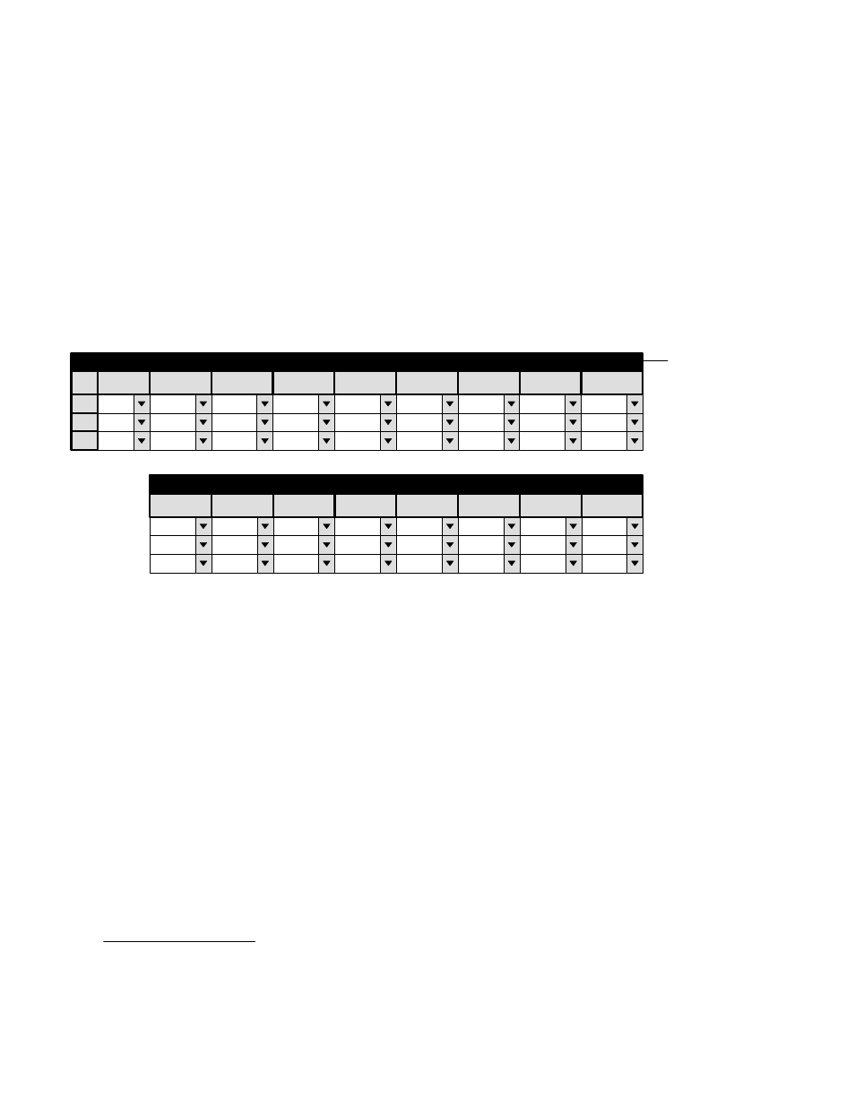
Figure 5−18. Serial protocol table (example).
Password
Network Description
Switcher Description
Control Panel Sets
Machines
TCS−1 Device Codes
Status Display Header
Tally
Path Finding
Exclusion
The VM 3000 has eight serial ports, and the SI 3000 has 16; but the protocol for these ports must be set in pairs. The protocol
setting on the menu shown above corresponds to the system shown on page 1−2. On SI 3000 SI1, ports 1 through 4 are config-
ured for Sony serial machines, ports 5 and 6 for MPK control panels, ports 7 and 8 for Ampex serial VTRs, and 9 and 10 for
ESbus machines (such as Philips D−1 VTRs).
The columns on the right side of the table show the baud rate setting for each port (or port pair).
†
‡
§
For details about CM 4000 applications, see CM 4000 Installation and Operating Manual.