Grass Valley VM 3000 System Controllers v.7.4 User Manual
Page 82
Advertising
Hardware Installation
2−10
VM 3000 Installation and Operating Manual
1
1
8
P1
DB15P
(male)
Shield (drain)
P2
DB15P
(male)
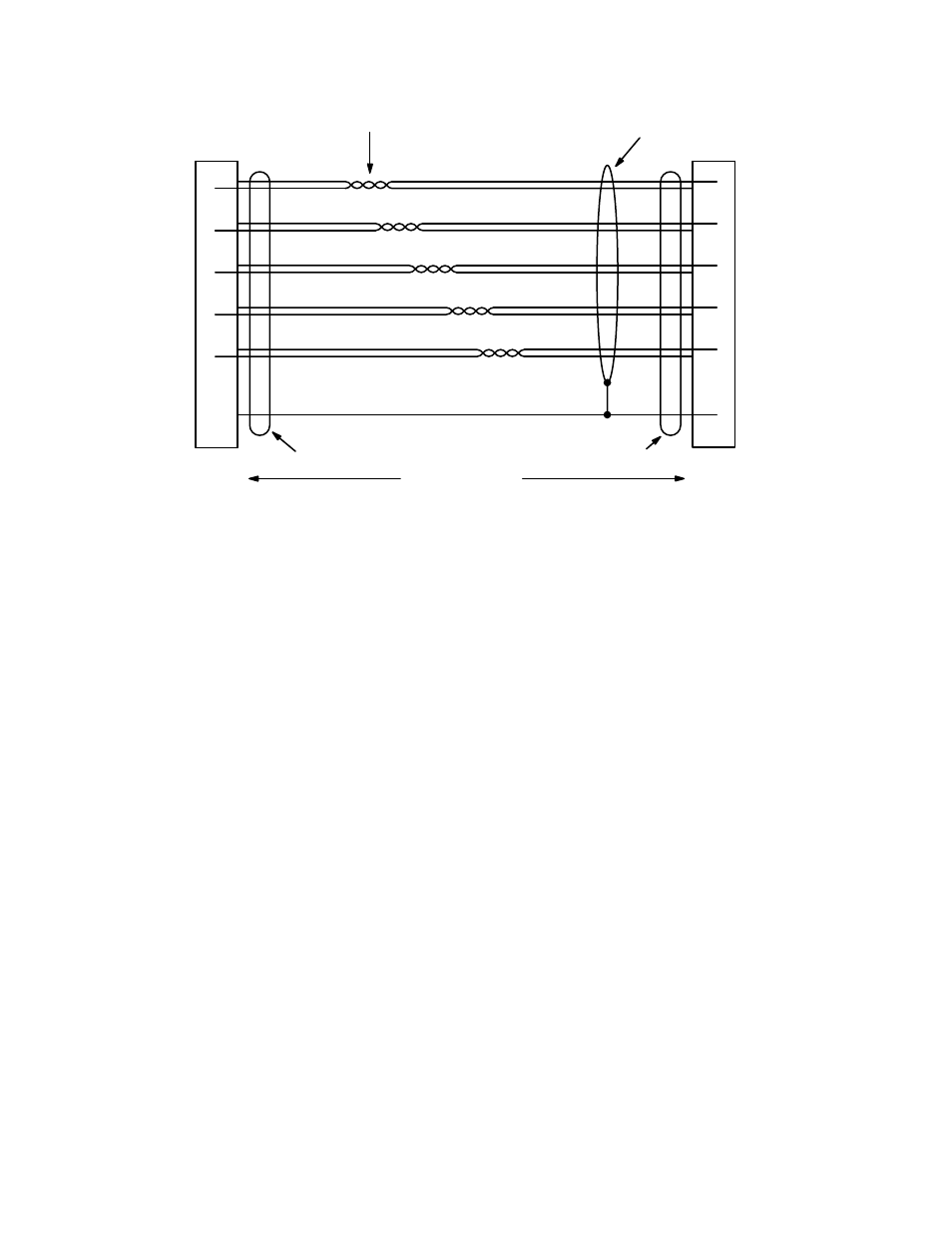
Figure 2−9. CC 2010 wiring. Reference: “Assembly, XPT Bus Cable Shield,” Grass Valley drawing no. 01−048592−TAB.
Red
9
Black
2
Yellow
10
Black
3
Green
11
Black
4
Blue
12
Black
5
White
13
Black
8
2
3
4
5
9
10
11
12
13
Twisted pairs
100 ft ( m) max
Shielded connector
Shielded connector
Shield
Red
Black
Yellow
Black
Green
Black
Blue
Black
White
Black
Reset
Data
Clock
Take
Confirm
Ground
Advertising
This manual is related to the following products: