And 5−125 – Grass Valley VM 3000 System Controllers v.7.4 User Manual
Page 335
Configurator
MPK Devices
5−125
VM 3000 Installation and Operating Manual
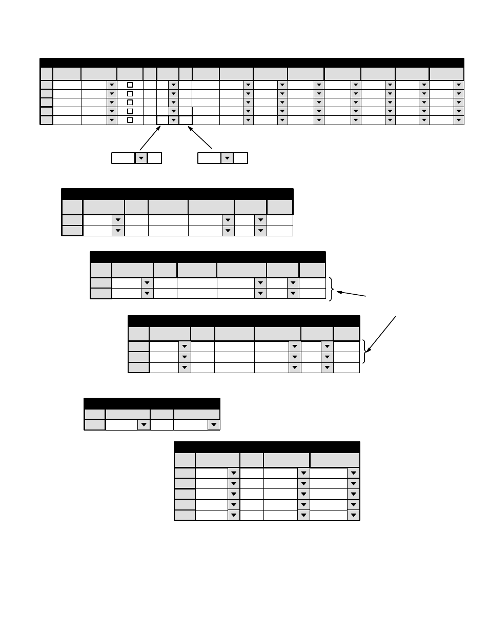
Figure 5−99. Tables for system shown on page 5−124.
Saturn application
MCS−2000 application
DVP−1
SD−PRST
UMD3A
4
00000032
PRESET
SD−PRGM
UMD3A
4
00000033
PROGRAM
SD−AIR
UMD3A
4
00000034
ONAIR
MCS_TLY
MCS_TALY
1
MPK Devices
MPK
Type
Expansion
Pass
Board
VM1
Port
Address
Input Sets
Output Sets
Level Set
Overide Set
Sequence Set
2
VM1
KXYZ−INP
KXYZ−LEV
3
5
VM1
Devices
word
In Panel
Out Panel
KXYZ−INP
KXYZ−LEV
KXYZ−LEV
KXYZ−INP
1
VM1
7
TALLY1
MI−3040/T
00000028
4
5
SI1
MCS−A
MCS−B
6
MCSBP
TALLY1
0
PROD1
TALLY1 /3
TALLY1
1
PROD2
TALLY1 /3
1
Tally Dependency
Tally Device
MCS_TLY
Opto
0
Output
Tally
2
3
MCS_TLY
1
MCS_TLY
4
5
3
PRD
1
Tally Relay
Tally Device
TALLY1
Relay
Logical Input
Logical
Device
1
Output Set — Program
Category
MISC
Entry
1
Mnemnonic
X
Output
MCS−A
2
MISC
0
X
MCS−B
These rows must be in
reverse order of the rows
in the Preset Output Set
†
Data in this field is not used, but an entry must be
selected to satisfy the Jupiter compiler.
x Data in this field is not used, but at least one charac-
ter must be entered to satisfy the compiler.
1
Output Set — Preset
Category
MISC
Entry
0
Mnemnonic
X
Output
MCS−B
Lev Set
Button
2
MISC
1
X
MCS−A
Button
Lev Set
1
Category
MISC
Entry
1
Mnemnonic
X
Output
MCS−A
Lev Set
Button
2
3
MISC
0
X
MCS−B
VTR
3
X
MCSBP
Output Set — On air
Logical
Logical
Logical
†
†
†
†
†
†
†