Figure 6, Terminal connections of bus line cables – HEIDENHAIN PROFIBUS-DP (DPV0) User Manual
Page 15
Encoder gateway installation
15
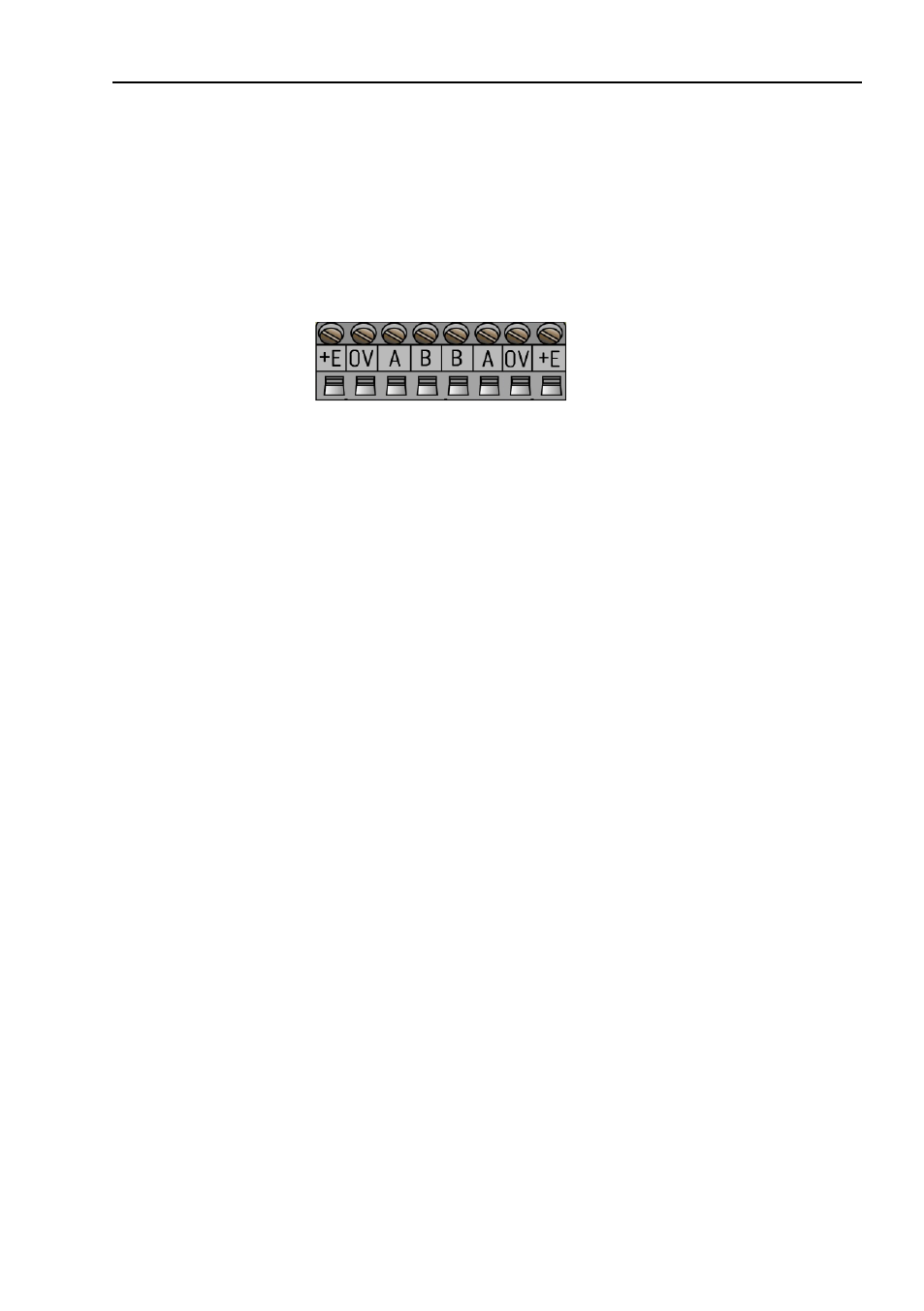
The cable gland gateway shall be equipped with twisted pair
shielded cable in accordance with EN 50170 and PROFIBUS
guidelines. The guidelines recommend a conductor area higher
than 0,34 mm
2
. Permissible outer cable diameter is ø 8 mm to
ø 10 mm for the bus lines cables. Located inside the back cover
are four screw terminals containing the required bus line
terminals marked A and B. Cable glands not used, should be
replaced with a M16 filler plug to ensure proper sealing.
Figure 6
Terminal connections of bus line cables
Note:
Tighten all screws in the terminal, even if no cable
has been attached.
Note:
The two A terminals are internally connected to
each other and the two B terminals are also
connected to each other so it does not matter to
which the bus lines are connected to.