Diagram i diagram j diagram k – ShoreLand'r SL70TAL V.1 User Manual
Page 16
Advertising
Midwest Industries, Inc.
Ida Grove, IA 51445
800.859.3028
www.shorelandr.com
0003355
REV C 2/14/06
Page 16
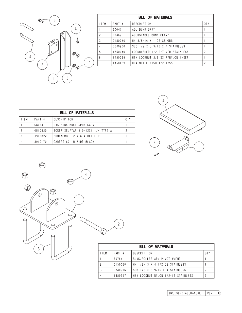
Diagram I
Diagram J
Diagram K
Stabilizer Bunk Assembly
The short stabilizer bunk in Diagram J is attached to the adjust-
able bunk bracket on the front cross member (See Diagram I) with
a 3/8” X 1” stainless steel hex bolt and 3/8” stainless steel lock nut.
Tighten, but do not over tighten so that the bunk can be rotated
to conform to the boat hull. Repeat on the other bracket.
Advertising
This manual is related to the following products: