Diagram f chassis diagram, Detail a – ShoreLand'r SL70TAL V.1 User Manual
Page 8
Midwest Industries, Inc.
Ida Grove, IA 51445
800.859.3028
www.shorelandr.com
0003355
REV C 2/14/06
Page 8
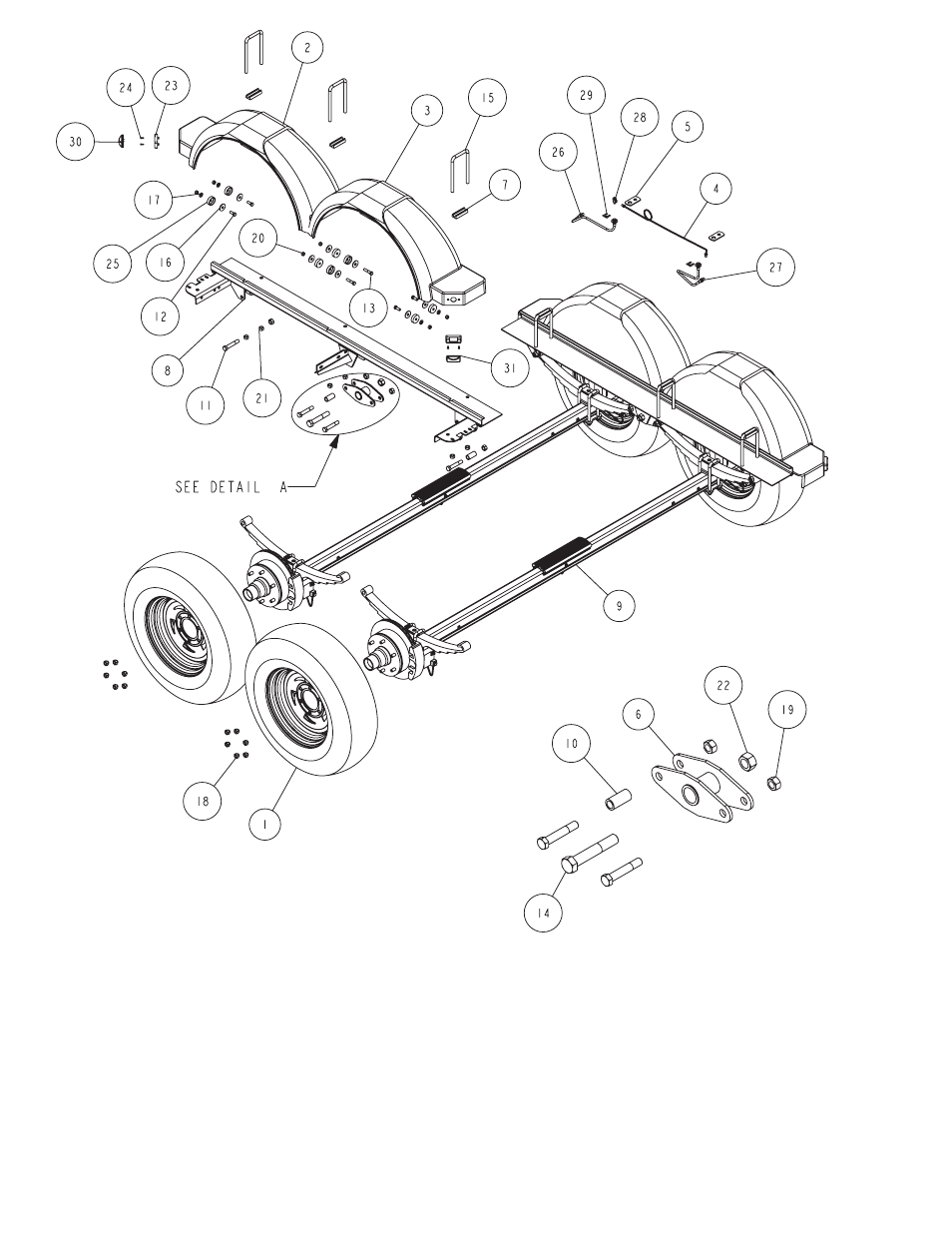
Diagram F
Chassis Diagram
Rocker Bogie:
Note there is a grease zerk in the center bushing of the rocker
bogie. Position the rocker bogie into the center mounting
channel of the spring bracket so that the grease zerk is
pointing down. This is necessary so that it can be serviced
in the field when needed. Align the center hole of the rocker
(6239210) with the center hole of the spring bracket. Insert and
secure with a 3/4” X 4-1/2” stainless steel hex bolt from the out-
side in and tighten with a 3/4” stainless steel hex lock nut.
Axles:
Note: The hook end of the springs must point to the rear of the
trailer, on both axles!
Position the axles so they are properly aligned with the trailer. Posi-
tion the brake axle so that the disc brake calipers are on the back
side of the axle. Place the springs on the topside of the spring pads
welded to the axle. (See axle assembly drawing on page 6). Place
a spring clamp on the top center of the spring. Place the 1/2” x 6-
1/2” stainless steel square U-bolts down over the top of the spring
clamp, spring and axle.
Place the spring and axle U-bolt plate (Item #6) onto the ends of
the two U-bolts. Secure in place with 1/2” stainless steel lock nuts.
Thread onto the U-bolts but do not tighten securely until the complete
unit is in position on the trailer. Repeat on the other spring.
Place one of the spring bracket bushings into the rear of the
spring bracket and secure with a 9/16” x 3 1/4” stain-
less steel hex bolt and 9/16” stainless steel hex
lock nut. Repeat in other spring bracket.
Position the rear axle under the frame, hook the hook loop of the
Detail A