3 power-generating unit protection test, 2 calculating the reference voltage – SMA SC 500CP XT Service Manual User Manual
Page 10
3 Power-Generating Unit Protection Test
SMA Solar Technology AG
10
SCCPXT_EZE-SG-en-11
Instructions for the Protection Test of the Power-Generating Unit
3 Power-Generating Unit Protection Test
The power-generating unit protection test is a fundamental part of PV system certification. For existing system the
protection test is part of the certificate, for new systems it is part of the declaration of conformity. It helps grid operators
and the certifying body to understand the proper parameterization and function of the protection concept. To this end,
the test procedure must be documented completely.
The parameterization specifications and the accuracy class requirements can be found in the grid connection guidelines
or are specified by the grid operator.
3.1 Safety during the Power-Generating Unit Protection Test
3.2 Calculating the Reference Voltage
An appropriate reference voltage must be selected for the testing device when performing the protection test. The
reference voltage can be calculated with the following formula.
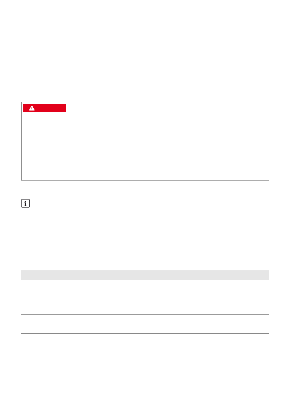
'$1*(5
Danger to life from electric shock due to live voltage
High voltages are present in the live components of the Sunny Central. Touching live components results in death or
serious injury due to electric shock.
• When working in a high contact-risk environment, wear personal protective equipment.
• Do not touch any live components.
• Follow the instructions precisely.
• Observe all warning messages on the product and in the documentation.
• Observe all safety information of the module manufacturer.
Contractually agreed voltage V
C
corresponds to parameter VRtg
The contractually agreed voltage at the grid feed-in point V
C
corresponds to the parameter VRtg.
V
C
– the voltage contractually agreed on with the electric utility company – must be entered for the parameter VRtg
during commissioning and calculation of the reference voltage.
Formula symbol Unit
Explanation
V
0
V
Reference voltage of testing device
V
C
V
Voltage at grid feed-in point, contractually agreed with grid operator
i
-
Transmission ratio of MV transformer. It results from the ratio of TrfVolExLo to
TrfVolExHi.
VRtg*
* This parameter takes the level of the medium voltage into account. V
C
, the voltage at the grid feed-in point as contractually agreed with the
grid operator, must be entered for VRtg.
V
Nominal line voltage of the utility grid (parameter)
TrfVolExLo**
** These parameters take the transformation ratio of the tap changer of the MV transformer into account. During commissioning, the tap changer
is adjusted in such way that the terminal voltage of the MV transformer matches the nominal voltage of the inverter as closely as possible.
V
Voltage on undervoltage side of external transformer (parameter)
V
Voltage on overvoltage side of external transformer (parameter)
V
0
V
C
x 1
i
------
VRtg x TrfVolExLo
TrfVolExHi
-------------------------------------------------
=
=