Yaskawa A1000 AC Drive User Manual
Page 8
2 Overvoltage Suppression A1000 Custom Software
8
YASKAWA TM.A1000SW.062 Overvoltage Suppression A1000 Custom Software Supplement
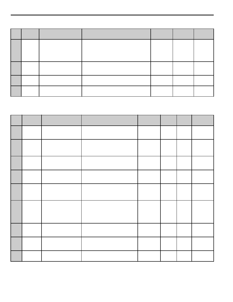
Table 2 Parameter Default Changes
Table 3 Overvoltage Suppression and Torque Ramp During Start Parameters
No.
MEMOBUS/
Modbus
Address
Name
Digital Operator Display
Description
Units
Range
Default
Value
A1-02
<1> Following 2 or 3-wire initialization (A1-03 = 2220/3330) this parameter will appear in modified constants.
0102h
Control Method Selection
Control Method
0: V/F
1: V/F w/PG
2: Open Loop Vector
3: Flux Vector
Note: The OV Suppression function is only available
in V/f and Open Loop Vector (A1-02 = 0 or 2).
-
0 to 3
0
b1-03
0182h
Stopping Method Selection
Stopping Method
0: Ramp to Stop
1: Coast to Stop
2: DC Injection to Stop
3: Coast to Stop With Timer
-
0 to 3
1
E1-04
<2> Default setting is determined by the control mode. When using PM motors, the default setting is determined by the motor code set to E5-01.
0303h
Maximum Output Frequency
Max Frequency
Maximum frequency that the drive will output.
0.1 Hz
40.0 to 400.0
90.0
E3-04
031Ah
Motor 2 Maximum Output
Frequency
Max Frequency
The maximum frequency that the drive will output to
the motor during motor 2 operation.
0.1 Hz
40.0 to 400.0
90.0
No.
MEMOBUS/
Modbus
Address
Name
Digital Operator Display
Description
Range
Default
Value
Change
During
Run
Control
Method/
Access Level
P1-01
0600h
Overvoltage Suppression
Selection
OVS Select
Enables or disables the overvoltage
suppression function.
0: Disabled
1: Enabled
0 to 1
0
No
– – – – Y– Y
P1-02
0601h
OV Suppression PI Setpoint
(Iq)
OVS Reg Setpoint
This parameter sets the OV Suppression PI
setpoint in percent of motor torque-
producing current (Iq). Iq is calculated based
on FLA & NLA.
Note: 100% Iq = 100% motor rated torque.
-100.0 to
100.0 %
8.0
Yes
– – – – Y– Y
P1-03
0602h
OVS Regulator Gain
OVS Gain
This parameter sets the gain of the OVS PI
controller. This determines the
responsiveness of the Iq regulator. A larger
setting equals more responsiveness.
0.0 to 25.00
2.80
Yes
– – – – Y – Y
P1-04
0603h
OVS Regulator Integral Time
OVS I Time
This parameter sets the integral time of the
OVS PI controller. This determines the
responsiveness of the Iq regulator. A smaller
setting equals more responsiveness.
0.00 to 160.00
0.10 sec
Yes
– – – – Y – Y
P1-05
0604h
OV Suppression Positive
Integral Limit
OV Reg I Limit
This parameter sets the positive limit of the
integrator in the OV Suppression PI
controller.
Note: 100% = Fmax (E1-04).
0.0 to 100.0
100.0 %
No
– – – – Y – Y
P1-06
0605h
OV Suppression Positive
Overall Limit
OV Reg Limit
This parameter sets the positive limit of the
OV Suppression PI controller (P+I).
Note: 100% = Fmax (E1-04).
Note: A setting of 0.0% disables the OV
Suppression PI controller.
0.0 to 100.0
100.0 %
No
– – – – Y – Y
P1-07
0606h
OVS Regulator Feedback
Filter
Feedback Filter
This parameter sets the 1st order filter time
of the motor torque-producing current
feedback. A larger setting equals a more
filtered feedback but less responsiveness.
5 to 10000
30 msec
Yes
– – – – Y – Y
P1-08
0607h
OVS Regulator Gain
Frequency
OVS Gain Freq
Gain change endpoint.
0.00 to 400.00 Hz 90.00 Hz
Yes
– – – – Y– Y
P1-09
0608h
OVS Regulator Gain
Multiplier
OVS Gain Mult
This parameter sets gain multiplier for the
OV regulator gain based on output
frequency.
1.000 to 10.000
1.300
Yes
– – – – Y– Y