Caution, Gpd or vcd drive, Do-08 board – Yaskawa DS383 User Manual
Page 3
DWG. NO. 02Y00025-0350
SHEET NO. 3 OF 6
R E L . 0 5 / 0 5 / 9 3
( m - df )
Refer to Sheet 1 for latest change.
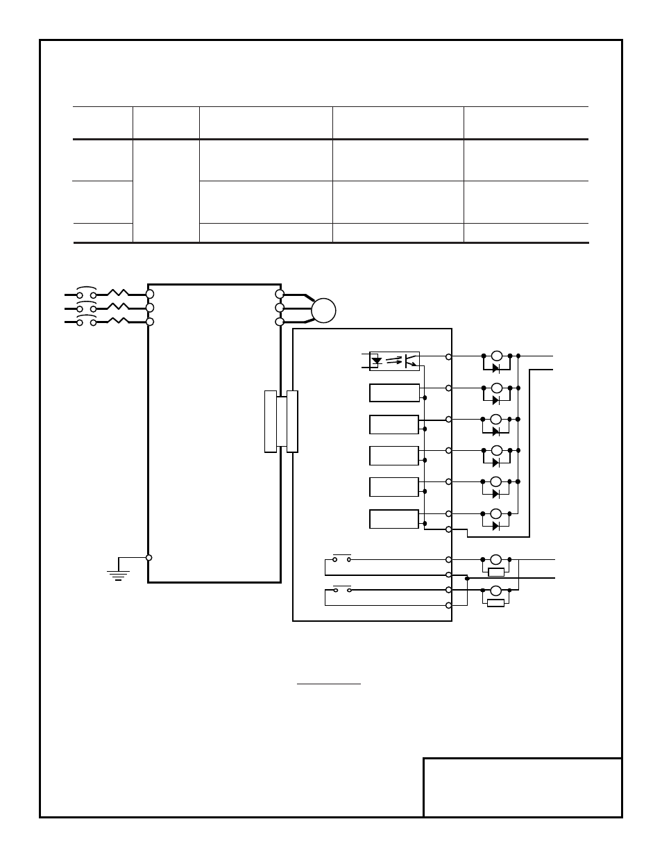
Figure 3. Interconnection for Digital Output (DO-08) Circuit
GPD
OR
VCD
DRIVE
L1 (R)
L2 (S)
L3 (T)
T1 (U)
T2 (V)
T3 (W)
E
TD5
TD6
TD7
TD8
TD9
TD10
TD11
TD1
TD2
TD3
TD4
DO-08
BOARD
PHOTOCOUPLER
I M
MOTOR
MCCB
3CN
3CN
Attention must be paid to diode polarity.
*
Be sure to mount a surge absorbing circuit.
**
RELAYS
K2
K1
RC
RC
8RY
7RY
6RY
5RY
4RY
3RY
2RY
1RY
*
**
+24VDC
0V
200VAC
Table 2. Terminal Functions of Digital Output Card DO-08
Terminal Terminal
Function
Capacity
Output
No. Screw Size
Signals
TD1
Relay contact output:
250 Vac, 1A or less
See “Adjustments”
to
2 outputs (independent)
30 Vdc, 1A or less
(INSTALLATION step 6)
TD4
TD5
M3 Photocoupler output:
48 Vdc, 50mA or less
See “Adjustments”
to
6 outputs
(INSTALLATION step 6)
TD10
TD11
Output Common, 0V
——
——
5. Wiring. See Figure 3 for Digital Output connections. See Table 2 for terminal functions.
CAUTION
KEEP DIGITAL OUTPUT (I.E. CONTROL CIRCUIT) WIRING
SEPARATE FROM MAIN CIRCUIT INPUT/OUTPUT WIRING.